IBIS-AMI: Secure the AMI model and software with code signing

Preface:

During the weekly meetings of IBIS Advanced Technology Modeling (ATM) task group earlier this year, a participant proposed requirement of code signing the released IBIS-AMI models for identification and security consideration. While this direction was not pursued further at the end due to various considerations, several meeting attendees suggested it would be helpful if someone with experience in this process can share (e.g. at the IBIS summit etc). It just so happens that all SPISim’s digital downloads, including executable, patches and AMI models are digitally signed. Thus even though I am no computer security expert, I am writing this post to share some info. and our process for you, the AMI model maker, to consider. If you decide to go this route, this post may even help you saving hundreds or even thousands of dollars on certificate purchase (really!) So read on…

What is code signing:

According to the wikipedia [HERE], code signing is a process of digitally “signing” executables to confirm the software author and guarantee that the code has not been altered or corrupted since it was signed. That is, if say SPISim creates an application or an AMI model, digitally sign then release them, recipients will be able to verify that the binary files they have at hand, regardless how they obtained them, are the originals. (I will use “software” to represent both executable and AMI models from this point as they are all binaries with programs.) If the software’s content was tampered … such as becoming corrupted during downloading or injected with malicious instructions, the digital signatures of the software will no longer be valid. This will be detected by the operating system or UAC (user account control). The digital signature is embedded inside the software. It only guarantees the source of the files but not their behaviors. So software may still have bugs or crash… only that you know who is the author to blame 🙂

Code signing makes use of asymmetric cipher (public/private key) algorithm. The private key file, i.e. a certificate, is a platform neutral. However, the code signing process itself is platform dependent. So windows’ software needs to be signed on windows and so are on OSX. Linux is a little different on this aspect, you will find more info. about this at the wikipedia link above.

In the subsequent sections, I will be using windows platform as an example.

What does signed software look like:

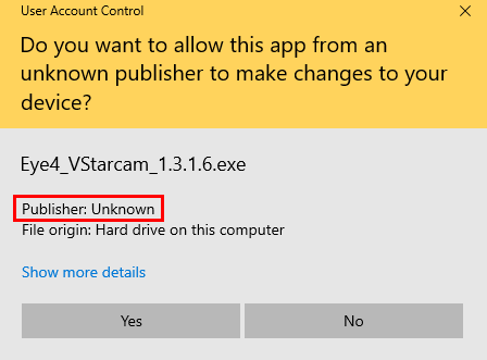
If your software is unsigned… such as the application shown below, users will see a “Publisher Unknown” info with yellow background. This may raise a red flag depending on your company’s IT or computer’s UAC policy settings.
 

On the other hand, a signed application like ours will look like this (blue):
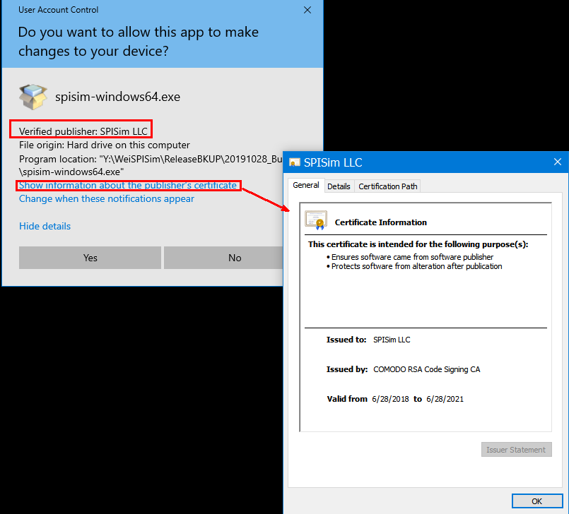
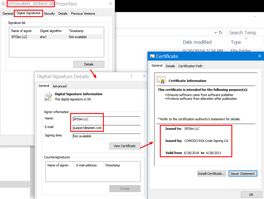
Besides showing “Verified”, more info such as company name, address, certificate issuer, valid periods etc are also available upon request as it’s embedded in the software.

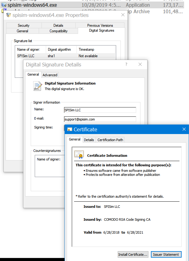
Actually, as soon as you download a software application, you may right click to verify their “Digital Signatures”. Only signed binary will have such tab available:
For signed web based application, such as our SPISim_AMI and SPISim_LINK free web apps, browser like chrome will let user run them directly. An unsigned or self-signed (more on this later) web-apps will mostly be blocked.

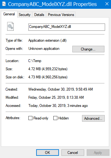
Regarding .dll (e.g. IBIS-AMI models),  an unsigned one will not have any source info:
A signed one will look like this:
 

Why you should have your software signed:

For a desktop or server based application, platform mechanism such as windows’ UAC will detect the signature during the initial installation process. For a web-based application, browser serves as a gatekeeper to detect or even block unsigned ones being run as they present more/frequent dangers. For a .dll file such as IBIS-AMI model, users need to right-click the file and check its properties by themselves unless the application which loads these dlls will check first before executing APIs within. At this time point, I am not aware of any EDA tool or simulator which does so. Nevertheless, code signing your software is like putting a seal of approval. It makes your product look more professional and also shows that as a software or model publisher, you care about customers or clients’ cyber security when your product is being used.

How to have your software signed:

Now that you are interested in getting software signed, here are the process:

  • Purchase a certificate:

You will need to have a certificate (i.e. private key) to sign the software. Your identity will be encrypted within this private key. Only a reputable entity can serve as a certificate authority (CA) and issue such certificate. One used to be able to create a self-signed certificate but that may be only useful within same organization (intranet). For public network, this entity will verify who you say you are before encrypting the identity you have provided using their own key (i.e. they vouch for your info) as a certificate. This is like a chain of trust. This way you can’t pretend that you are Microsoft or Google etc. This is a very involved process with human effort included so it may not be cheap!! By the way, a certificate is not forever… it expires after certain period of time.

If you search  “purchase certificate for code signing” online, those top ones are probably quite expensive:
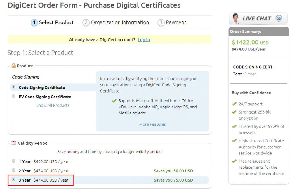
I am going to save you money here… Visit tucows.com, open an account and purchase certificate there. In stead of thousands, you pay less than two hundred for a three-year certificate!

  • Validate your identification:

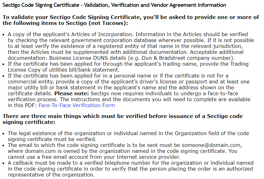
During the purchasing process, you will be asked to provide identity such as your personal or company name, company email address, phone number, phsical address etc. All the info. provided must be verifiable by this entity you are purchasing from. For example, you will need to have a public (government or state) record which shows same information. You may be asked to provide IDs and verify you are the domain owner. You will then be asked to wait for a period of time or even possible phone call from the CA. They will go through human based verification process to make sure the data you provided is valid and you are who you say you are. Only after that, they will email you the link to download/install the certificate they have issued for you. A supported web browser like FireFox is required to install the issued certificate.

For example, here is the info. requested during the purchasing process:
  • Download and backup certificate

The issued certificate will delivered via a clickable link and can only be installed in the same browser used during application/purchasing process. It is very important that you install, export this certificate right away then backup to a different location. With backup certificate, you can use other computer to sign software or the same computer after OS re-install. You will also need this certificate as a file as part of the building and release process.

More info. about how to do this is available [HERE]

  • Make code signing part of your build/release process

Once the certificate file is available, you may incorporate that into part of software releasing flow by signing and verifying the signature at the end of the building process. This is platform and OS-bit (32-bit or 64-bit) dependent. The white blocks below are password I used for using our certificate..

Signing and verify IBIS-AMI dll file:

Signing web-app jar file:

Signing and verify installer:

Time-stamp using a NNTP server is required:

Signtool64 above is a windows’s tool from Microsoft. Java has its own version:


Unsign signed software:

Because a certificate is valid only though certain period of time(e.g. three years), it will “expire” after that. While not immediately after the expiration date, you will soon not be able to sign the software with expired certificate. The time-stamping via a time-server during the signing process is a mechanism to prevent you back-date the software to be released…. That means you will need to keep certificate updated by re-purchase a new one. Platform such as windows’ UAC may also prevent one from installing software signed by outdated certificate. The last possibility is that a certificate may be revoked due to the “chain of trust” being destroyed somewhere upstream.

More often than not, once an AMI model is released, it may stay out there beyond original publisher’s control for quite some time and then become expired. A signed software can be un-signed to strip this timestamped signature if the IT policies prohibit installing outdated binaries: More info. may be obtained [HERE]

Finally:

I hope this blog post will be helpful for model maker publishing their AMI models or software alike. Another good blog article on this topic may be found [HERE]

IBIS’s package model

Recently I gave a training to some of our customers regarding package model handling in an IBIS file/model. Most of the treatments in this topic fall within IBIS spec., extraction and simulator tools used, rather than modeling tool like our modeling suite or SPIBPro. Thus I think it will be beneficial to organize the materials and share through this blog post, while serving as a future reference for our customers.

Package model:

An IBIS file may contain one or more IBIS models. Each of the IBIS models has its own IT or VT tables to describe the behavior of the Tx or Rx silicon design attached to that signal pin. The effect of the package model, on the other hand, is not included in those table data. Information about the package model is “linked” with the silicon portion of the buffer through either IBIS keywords within the same IBIS file, or as a separated file in different formats. It’s the simulator’s job to take both the separated Tx/Rx silicon behavior, as well as package model into account during circuit simulation.

In general, there are two ways to link the IBIS’s silicon behavior with the package model. Each also have two possible routes to achieve the same purpose:

Add package model info:

    1. Inside an IBIS file:
      • As a lumped model
      • As a distributed model
    2. Outside an IBIS file:
      • ICM (IBIS Interconnect Modeling)
      • General spice circuit elements

More details will be discussed below… Please note that these package models should be generated from extraction tool such as HFSS, Q3d etc. The IBIS model or file mentioned here simply serves as a place holder. Circuit simulator will use all these data together during simulation.


Package as a lumped model inside an IBIS model:

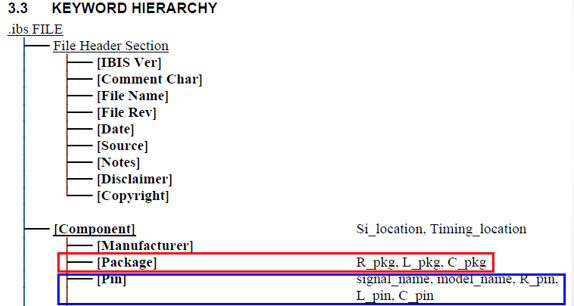
From the IBIS spec, we can see two related keywords for this lumped model representations: [Package] and  [Pin]

To be more specific, please see this example model:

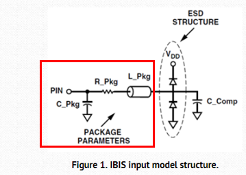
These values represent the parasitic structures as shown below:

This is the simplest, yet least accurate, method to describe the package information. While the [Package] keyword and data is required, parasitic portion of the [Pin] keyword is optional. When both are present, those in the [Pin] section will superseded (i.e. override) values defined in the [Package] section. Thus, a model maker can use [Pin] keyword to introduce pin specific lumped parasitics while using [Package] keyword for general or default values.


Package as a distributed model inside an IBIS file:

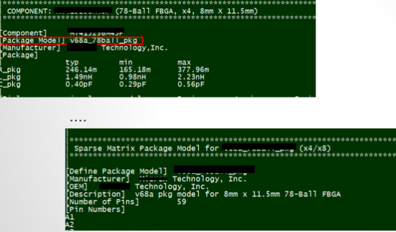
A more comprehensive (distributed) package model may be introduced into an IBIS file and model using the [Package Model] and [Defined Package Model] keywords:

Using this method, the component declares the name of a package model it is using (thus the value of the [Package Model] is simply a model name string), and the detailed contents of this package model is defined as a separated section using top-level keyword, [Define Package Model] inside the same IBIS file (usually toward the end of the file, after all [Component] descriptions):

What’s in side the defined package model? Since it’s a “distributed” model and belongs to a component, terminals mapped to a component’s pins are there and so are frequency dependent R/L/G/C matrices etc. The dimension of the matrices is equivalent to the number of pins mapped. With that said, a S-parameter format is not supported here. To use a S-parameter as a package model, one must use either of the remaining two methods to be described below.

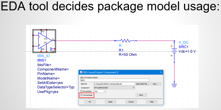
As mentioned earlier, an IBIS file or an IBIS model which has package model info. is just serving as a place holder. Package model’s effects or behaviors are not included in an IBIS model’s IV/VT/IT table data. Simulator has the responsibility to combine these two together… either when computing switching coefficients for lumped model version or “stamping” extra elements into nodal matrices for a distributed one. This also means that different EDA tool may have different methods, syntax or GUIs to introduce package model’s data:


Use ICM as a separated file for package model outside an IBIS file:

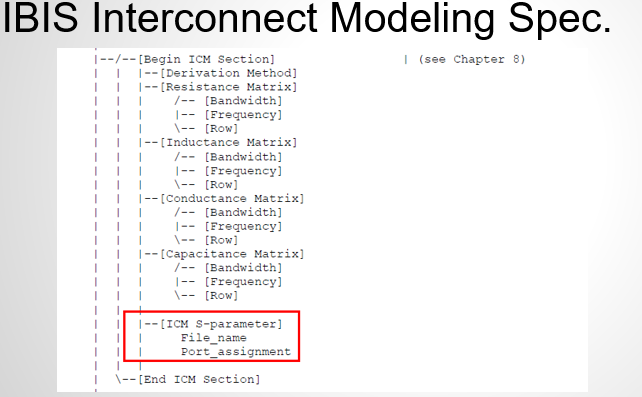
The ICM (IBIS interconnect modeling) spec. is a separated “top-level” spec. document similar to an IBIS spec. So to learn more about it, one has to read the through ICM spec. document

While it’s more or less similar to the [Defined Package Model] mentioned earlier in terms of R/L/G/C frequency dependent matrices etc, it has one unique strength in particular that it supports S-parameter:

So if your extraction tool can only produce S-paramter format, then ICM is the way to go. The table below lists the comparison of different interconnect model format: (PKG is the defined package model)

Use general circuit description for package model outside an IBIS file:

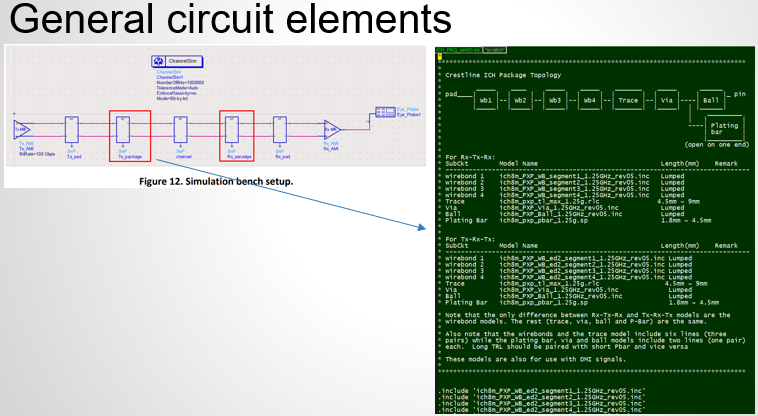
Last but not least… one may also introduce package model contents using a non IBIS/ICM specific format. For example, a model maker may provide a spice .subckt representing the package model (converted from frequency data using tool like broadband Spice or IDEM work etc, can have further hierarchy) or a simple S-parameter. The connectivity should be documented in the simulation guide or usage manual of the IBIS model. It’s the end user’s responsibility to put this as one of the stages in simulation topology. For example, Intel’s platform design guide use such method for an ICH package model:

There are pros and cons for this approach: a model user may have more work to have package effects introduced. On the other hand, this method has best compatibility… it does not require supports of a specific IBIS/ICM version in the simulator used, and it also allows probing or sweeping internals inside the package model for debugging or optimization purpose.

Differential modeling flow: Revisit

In the past, we have blogged several articles regarding buffer modeling. The flow and focus there are mainly for single-ended. The considerations are that:

  • Single ended (SE) buffer modeling is a good introduction to modeling flow in general without further complication;
  • (Pseudo) differential buffer can actually be modeled as two single-ended buffers;
  • Many (true/half) differential buffer can be modeled like pseudo differential buffer without significant loss of accuracy [LINK]
  • Differential buffer modeling involve several steps which are a little more complicated.

During our workshops in Taiwan last month, several attendees asked about CML (current-mode logic) modeling. With the maturing of the concepts in SE modeling and the prevalence of SERDES interfaces such as USB, SATA, PCIe etc, we think it’s a good time to revisit the differential modeling flow in more details. We will also show how this design concepts are realized in our SPIBPro in next post.

Note that the contents of this and next posts are also written in conjunction with the paper submission to the IBIS summit later this year.

Model descriptions:

[The info. here are summarized from the IBIS cookbook V4]

A differential buffer can be categorized into three different types:

  • Pseudo differential: shown in the rightmost of the picture below. The “P” and “N” driving portion are mutually independent. There is no coupling between these two pins in the circuit.
  • Half differential: shown in the middle. the pull-down portion of the “P” and “N” are coupled via a current source or shared load.
  • True differential: shown in the leftmost. Both the pull-up and pull-down circuits are coupled via “current-mirror” and shared current source.

DiffBuffer

For pseudo differential type buffer, the single ended buffer modeling flow can be applied directly. One only needs to generate these two “uncoupled” buffer separately (or use the same model with input flipped) and describe their differential behavior using the “diff pin” IBIS keyword:

DiffPin

Note that this “Diff Pin” keyword is also optional. So one may also simply instantiates two instance of the single ended buffer and use them together outside the IBIS file, such as in the spice netlist.

True/half differential buffer:

For a true/half differential buffers, the existence of “coupling” between P and N circuits must be described using existing IBIS syntax. There are two ways to do so: either using “series” or “external model” keywords:

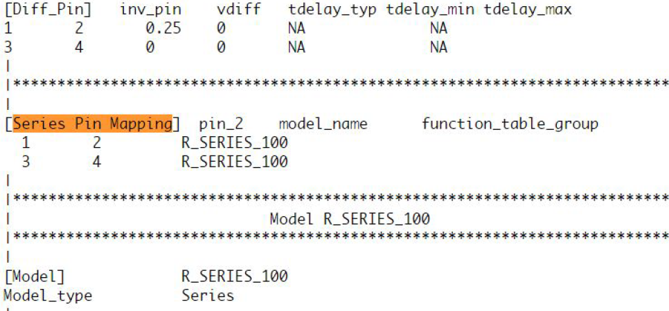
  • Series: There are two places series needs to be declared: the first one is “[series pin mapping]” in the model headers and the other one is “series model” of the “coupling” circuit in the “[model]” descriptions:SerPinTake the picture shown above as an example. Under the “Series Pin Mapping” keyword, a model named “R_SERIES_100” is declared to connect pin 1 to and 2. Another instance of such model also sit between pin 3 and 4. Pin 1~4 each has its own model defined in other part of the ibis file already. For example, pin 1, 2 may have an output buffer connected while pin 3, 4 have open-drain buffers. This R_SERIES_100 model must have type “Series” defined as part of the IBIS file. Since “Series” is one of predefined IBIS model type, its contents (keywords) are not free form and must be one or more of the following series elements: R, L, C, Series current and Series MOSFET which contains up to 100 I/V tables under different biasing voltages.SerElem
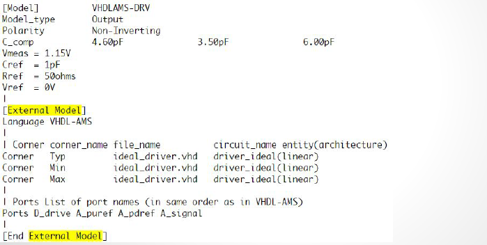
  • External Model:  In the IBIS spec, four different differential specific model types are also support.:DiffMdlTypeThese differential model types must be implemented with language such as Spice, VHDL-AMS, Verlog-AMS, IBIS Interconnect Spice Sub-circuits (IBIS ISS) and declared with the “External” model section. These languages provides much more flexibility in terms of modeling capabilities, yet they also diminish the portability of the generated IBIS model.DiffMdlDescIn the example above, a separate file “ideal_driver.vhd” must be provided outside the IBIS file and an “entity” of name “driver_ideal” needs to be defined. The port connections is described using reserved keywords after the “Ports” statement. In the IBIS Spec, all possible ports are pre-defined and the declaring order here must match their definitions in the associated Verilog/VHDL etc file.
Modeling process:

Pure method 2 implementation, i.e. coding in language like Verilog/VHDL, is up to the model developer. On the other hand, the syntax and structure of series elements, used in method 1, is strictly limited. Thus the modeling process below focuses on method 1 above, i.e. the series model method.

As the coupled half/true buffer described by separated single drivers and connected via a series model for the coupling, the modeling flow must somehow be able to extract the data for these blocks independently so that they can be described with conformed IBIS keyword and reproduce the response when putting together.

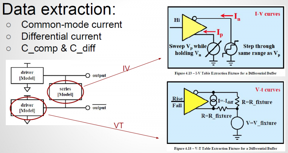
For the “Driver” block, it’s a generic input/output/IO type buffer. So tables such as pull-up/pull-down/power-clamp/ground-clamp, when applicable, must be extracted. So are the transient waveform under different test loads. The extraction must be done such that the coupling with other half can be separately as an independent “series element” model.DiffDrvDataExt

  • PU/PD: A two dimensional table produced by sweeping at both the P and N outputs are performed, as shown in the upper right block above. One major assumption for PU/PD extraction is that when both output pins are at the same voltage level, there will be no current flowing through the series model (i.e. the coupling portion). So in that condition, we can assume the series model does not exist at all. The current flows into or out of the buffer at that point is considered as “common-mode” current. This common-mode info is than extracted from surface table and modeled as pull-up and pull-down IV. The whole surface is then shifted vertically by subtracting this common-mode current at every x/y grids. The resulting surface table is considered as the differential current (resistance portion of the series model) and will affect the output when voltage at N and P are different. Note that to satisfy the aforementioned assumption of zero current through series element at common mode voltages, the sweep done at the P/N pins must step very slowly such that the charging/discharging of the reactive components, such as C_Comp or C_Diff can be neglected.
  • PC/GC: Clamp table in IBIS are always optional. On the other hand, when a circuit have current which always exist and can’t be turned-off, these data must go to PC/GC to avoid being double counted. That is, the PC/GC table must account for current which always exist and this current will be subtracted from the PU/PD table during the modeling process to avoid being double counted. Situations like this include the ESD circuitry and/or pull-up portion of the half-differential buffer. For PC/GC extraction, common mode sweep like that for PU/PD needs to be performed while buffer is disabled (put into high-Z state). The common mode current will then be extracted as the PC/GC table. Differential mode current is disregarded as it has been accounted for in the PU/PD differential data.DiffDrvCDifExt
  • C_Comp/C_Diff: An important step here is to extract and compute the differential capacitance, C_Diff. This has to be done before VT simulation. It is because C_Diff will affect the transient state differential current, thus it must be accounted for before VT transient simulation. The extracted value will be part of the series element model by adding as C_series. In real design, the C_Comp and C_Diff are both frequency and voltage dependent. So an user can perform 2D sweep in these two dimensions and select a proper value for C_Diff. This formula to calculate c_diff/c_comp is shown above.
  • VT waveform: With both static (resistive) data being processed from PU/PD/PC/GC simulation, and the reactive data, i.e. C_Diff, computed from the C_Die simulation. these two info can then be modeled together to be eliminated during VT simulation. The considerations is that: once the effect of coupling part is removed, then the remaining data can be considered as single ended and model accordingly. Having that said, reader should realize that there are much more details involved in this step. For example, how do you model these data? Two approaches may be considered:
    • Use E/F/G/H control element: the surface data can be fit to minimize the mean squared error. Resulting coefficients are then realized using poly function or like of a control sources.
    • Create a series element: decide the proper components and then create a series element.

Interested user may find some study presented in IBIS summit, such as [this one]

As one can see, the modeling process for a differential buffer is not linear and a certain order must be followed. Inaccurate common-mode extraction will affect IV tables and cause dc-mismatch of the steady state. In addition, failure to extract C_Diff and model different current accurately will greatly impact the accuracy of the transient data. We will see how a modeling flow should take these into account and be validated easily. These are also design concepts behind our SPIBPro flow.


Simulate IBIS Data with Free Spice [Part 2]

Note:

Interested reader of this post may also want to follow up with the [Part 1] of same topic and try out the [Free Web App] which realizes this conversion flow.

For the motivation behind our Ibis to spice development and Ramp based Ibis2Spice conversion flow, please see [previous post]

Waveform based Ibis2Spice conversion:

Typical IBIS model simulation makes use of its waveform data. Thus a converted spice model from its IBIS model must be able to use these timing related data to have good correlations .

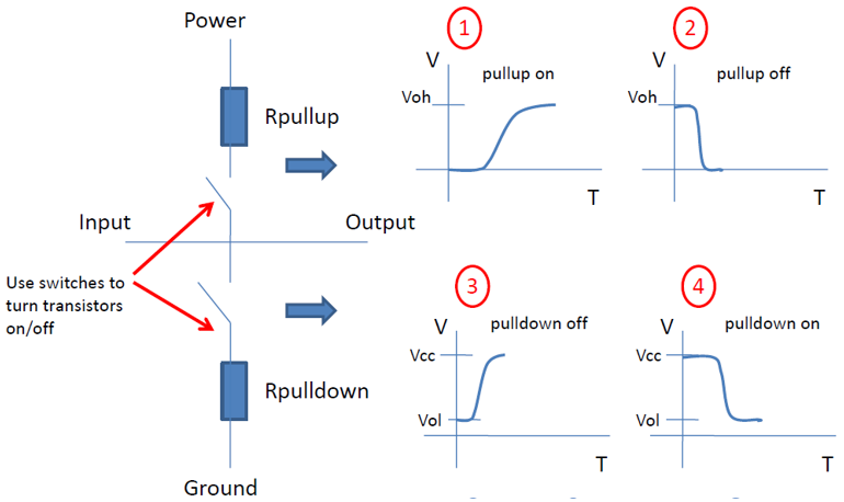
Both voltage and current related data can be timing related: In IBIS model of version 3.2 and up, one ore more “rising” and “falling” waveform may be included. Typically, two set of waveform under two different loading condition will be provided. In case only one waveform is available, simulator may convert ramp data to form additional set of waveform. In IBIS model version 5.1 and up, “composite current” is also included in order to account for simultaneous switching noise. This current information is point-to-point aligned with their voltage counterpart to withdraw current from power supply terminals of the buffer model. Note that what we call “timing” here is actually “elapsed time” after buffer’s input signal switches from low to high or high to low. Two sets of switching coefficients, Ku/Kd for rise and fall transition respectively, are used to mimic the gradually turning on/off the PU/PD branches such that under test load condition, the voltage and current waveform data can be reproduced accurately. By using these swtching coefficients, buffer’s strength will be scaled accordingly depending on the load. User may see [our past s post] for buffer’s operation in more details.

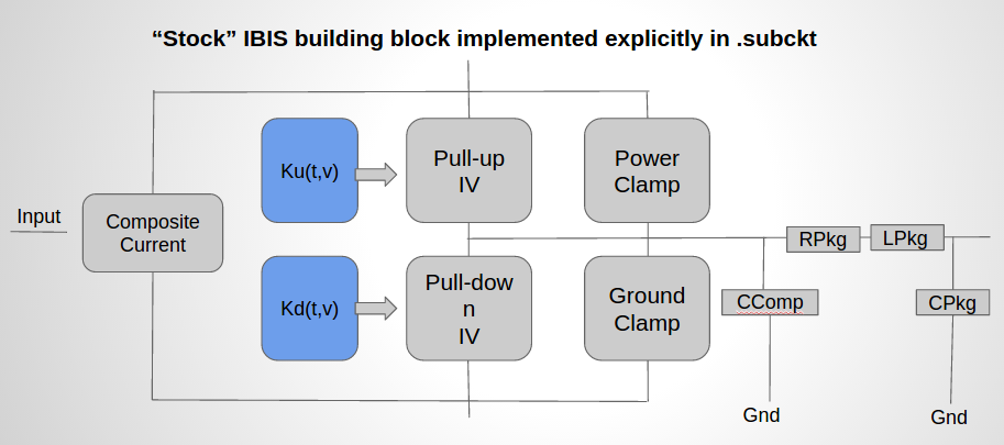
Once we have the related  info. then we can create building blocks and assembled exactly as  they are meant to be used in IBIS model, but now in spice format. So the schematic of our waveform based converted spice model will look exactly like a “stock” IBIS:

Selection_209

To achieve this, i.e. be able to use timing data in converted spice model and run like a stock IBIS, three main challenges need to be overcome:

  • Extract “elapsed time” info. during simulation;
  • Compute the switching coefficients Ku(t)/Kd(t) for both rise and fall transitions;
  • Assembled the block together and mimic actual IBIS operation.

Extract “elapsed time” info. during simulation:

In free spice (e.g. NgSpice)’s ASRC (Arbitrary SouRCe) element, function can be used.  One function parameter which may be used for this timing purpose is the “time” variable:

Selection_210

By using this “time” variable, we can calculate and extract the “elapsed time” info.:

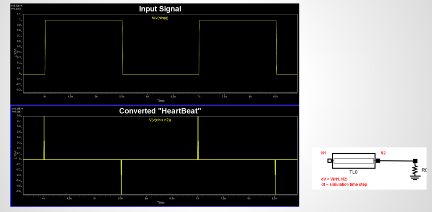
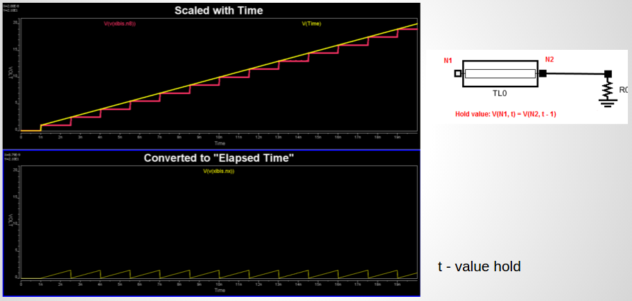
  1. First, we need to be able to differentiate between rising and falling from input. This is because both rising and falling transition needs its own Ku(t)/Kd(t) table. After converting input analog to a digital signal, we can use first directive such that rising and falling can be differentiated. To compute dv/dt, a transmission line (TLine) can be used. Other choice may include using a Laplace equation in control element to mimic the “delay”. The decision of using TLine for the delay is also because in free spice, the control element does not support “delay” parameter like other commercial simulator does. Measurement of voltage differentials across TLine gives us dv and TLine delay is a single simulation step dT. TLine is terminated with its characteristic impedance so no reflection will incur at the far end.Selection_211
  2.  Once rising and falling transitions are separated, we can multiply the converted dv/dt with “time” variable and also use a “latch” to hold the signal at the end of the transition. Again, we use a matched TLine as a “latch”: by feeding near end voltage with the far end one, which is data of previous time step, we can have a latch holding signal indefinitely. The latched signal is show in red of the upper plot below. With another “time” variable subtracting this latched signal, we can then obtain “elapsed” time as show in the lower half of the plot. One caveat is that in typical time domain simulation for SI/PI, time step is pico-second range. Spice will ignore variables of very small value, such as 1E-12 scale, thus a proper scaling will be necessary.Selection_212

Compute the switching coefficients Ku(t)/Kd(t):

With the elapsed time, t, now available, we can compute Ku(t)/Kd(t). There are numerous paper and presentation detailing the algorithms. For example, one may compute this switching coefficients from model data based on the first reference below, or use measured based approach based on spice simulation detailed in second reference:

  1. Extraction of Transient Behavioral Model of Digital I/O Buffers from IBIS, Peivand Tehrani et. al, 1996 Electronic Components and Technology Conference.
  2. General K-table Extraction w/ Spice, Bob Ross, IBIS Summit, DesignCon 2015

In general, waveform data from two different test loads are used to solve two unknowns at each time points during rising/falling transition. This calculation is done offline in advance and the resulting data are again realized in the form of ASRC devices. The PU/PD/PC/GC branches will be exactly PWL based ASRC, only that the PU/PD takes one more input (NKUX, NKDX below) which is the switching coefficients, Ku(t) and Kd(t):Selection_205

Ku/Kd are ASRC with pre-computed coefficients and variable of “elapsed time” computed from the first step:Selection_206

PU/PD branches draw associated  current based on the Ku/Kd value presented as voltage value at node 5 below:Selection_207

Assembled the block together in spice formats:

While netlisting different PU/PD/PC/GC/Ku/Kd blocks together is trivial, a nuance becomes apparent during validation: the assembled spice model will have “spikes” right before and after each transitions which makes the model unusable.

Further investigation reveals how devil is hiding in such details… As explained in our previous post, there is a “hand-off” during transitions:

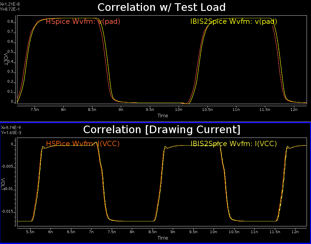
That is, when we “run out of” Ku/Kd for, say rising transition, we keep using the last point data until buffer is about to switch from high to low state. At that point, “hand-off” happens so that Ku/Kd for falling transition will be used. The “hand-off” process is triggered from input and even a time step delay in terms of table usage switching will cause huge spike and cause problem. With carefully looking into different signals in details and figure out their relation in timing, we have a solution which filters out all the spikes and produce a well correlated results, as shown below:

Selection_202

Both the voltage waveform and drawing current matches quite well. The small delay is insignificant because it’s a constant added to each cycle and will be eliminated in the eye plot.

As we introduce two single time step delay transmission line elements to calculate dv/dt and serve as sample-and-hold functions, they also limit the simulation time step a simulator can take. As a result, the converted model run much slower compare to its IBIS counterpart run in other commercial simulator under test load condition. In extracted channel simulation, the “slow down” becomes less apparent as there are multiple transmission line segments present in the topology. The time step limit introduced by the shortest transmission line is common to all simulators which may not be much longer than the TLines we have introduced.

Another note worth mentioning is that while this post focuses mainly about Ku/Kd and voltage waveform data, Composite current and their ISSO_PU/ISSO_PD are treated similarly: An ASRC constructed from composite current based on time aligned point with voltage counterpart is used to draw current. Another set of scaling table, based on ISSO data ares computed off line in advance in order to take the non-ideal voltage supply into account.

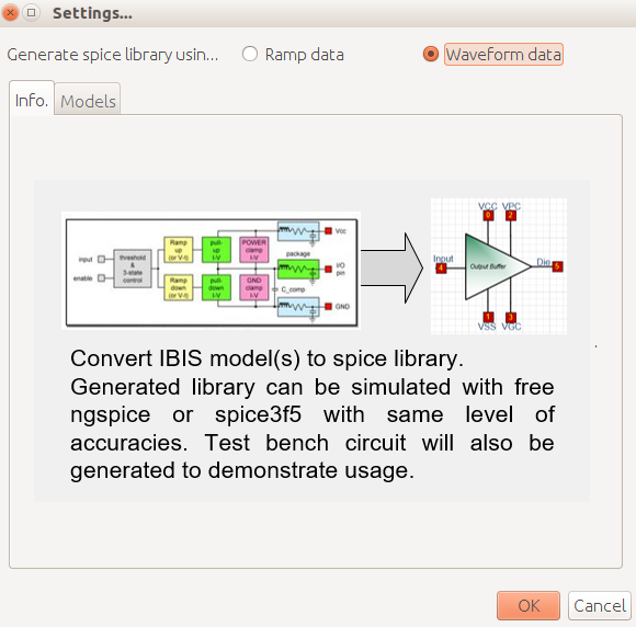
With both ramp and waveform based Ibis to spice flow being available, we are able to perform SI/PI simulation using IBIS on free spice simulators. Such flow has been integrated in our SPIBPro flow as shown below:

Ibis to Spice function is SPIBPro

Ibis to Spice function is SPIBPro

This post is written in preparation for the upcoming IBIS Summit at DesignCon 2016, where we will present this Ibis to spice flow. The presented slides and associated examples are shown below. Reader may also download them from IBIS's official page for this summit.

Presented slides: View externally [HERE]

Example files: [click to download]

IBIS model: What is buffer model and why IBIS

Before we are going to dive into details about buffer model, we need talk about why we care…

Buffers sit at the driving and receiving ends of a channel. So while the passive channel is composed of models like transmission lines, vias and connectors, the models sit at both ends are buffer.
Channel
If you are a circuit designer, in particular, a chipset designer, you pay attentions to the transistor sizing and the associated process, voltage and temperature corners (so called PVT corners) so that you will be assure that the designed buffer, when connected to the system, will have desired strength, impedance and timing.

Transistor and process info. for a buffer design

Transistor and process info. for a buffer design

However, if you are a system designer, or a signal integrity engineer. You pay attentions to higher level of the system design, such as component placement, routing, topology, termination etc. A buffer or an IC to you is just a component off the shelf. Those design details like transistor sizing, silicon doping concentration etc are too much details for you and are mostly not needed to what you are doing. Just like when software designer make connections between libraries, they make use of application interface (API). A much simplified model to represent these buffers are thus needed to enable system design.

Thus from the perspective of needs to interface between transistor level and system level design, a behavioral model representing a buffer is certainly needed.

System level design use buffer as component.

System level design use buffer as component.

Now when we talk about buffer modeling, there are several requirements derived from different perspectives:
A good buffer model needs to be:

  • Accurate: This is most important consideration. Garbage in, garbage out. By accurate, it’s usually considered to be within 5% tolerance of corresponding original, transistor design.
  • Protect IP: From IC/Chip set manufacturer’s perspective, they release buffer model mostly publicly to enable their customers adopt the design. However, they also do not want to reveal any IP such as how the buffer is designed and the manufacturing process info.
  • Run very fast: From system designer’s view, a buffer needs to run very fast, typically at 100X ~ 1000X of the corresponding transistor design. Only so then system design, which usually includes hundreds’ or even thousands’ of buffer, is made possible.
  • Easy to generate: For a model generation engineer’s perspective, if it takes lots of effort to generate and correlate the buffer model from its transistor counterparts, then the model generation process will become error prone and cause accuracy concern. Black-box type modeling is desired mostly as the model generation engineer does not need to know how these buffers are designed yet he/she can still generate buffer model which matches its original transistor’s performance.
  • Follow industry standard: A good buffer model should follow industrial spec. or format such that it can be simulated with different vendor’s tool, such as Synopsis’s Hspice, Cadence’s SystemSI or Agilent’s ADS. A model locked in to a particular tool is usually just to hide potential accuracy and easy generation issues down the road.Often in such considerations, one may consider using encrypted transistor netlist, such as encrypted Hspice, for model release. However, this will defeat the requirement of speedy simulation performance as encrypted model is usually run at the same speed of their transistor originals.From these considerations, several industrial standard have been proposed and widely used for buffer modeling used in system level analysis. They includes: IBIS and Verilog-A. In which, IBIS is most widely used and has been around since mid 1990. More info. about IBIS spec can be obtained from the ANSI’s IBIS website [HERE].

What is a system:

System integrities include signal integrity (SI), power integrity (PI) and electro-magnetic compatibilities (EMC) in general. They are analyzed via circuit modeling and simulations. However, what is the scope of a system?

20120126_01

Fig.1 is a typical pc mainboard we usually see. There are many components, such as heat sinks, various capacitors and connectors on the board’s top layer. When flipped over, we also see that there are many solder points and routing traces like Fig. 2. System like this is the scope of our analysis. Note that it doesn’t have to be a PC system… mobile phone, embedded devices or even high-end server are also treated the same. They are just different in terms of circuit size and scale.


20120126_02

These systems are designed with CAD software (Fig. 3) When we zoom in part of the schematic, we will find many routing traces extended from the chip’s pins’ locations to the edge of the board… usually where the connectors are located. (Fig. 4)


20120126_03

If we further zoom in to the edges around these chip’s pins, and visually in a 3D view (Fig. 5), One may see that there are many vertical cylinders making transitions between different layers. As a package and sometimes sockets sit between silicon chip and underlying mainboard, and a system board is also mostly composed of more than top and bottom layers. These cylinders are called “Via”. A cross-section view makes these via transitions more clear. Conducting traces are extended outwards like roads carrying electrons leaving the central hub.


20120126_04

Moving upstream toward inside the chip, we will be marching into the silicon world where designs are mostly realized with MOSFETs. Logics are computed and bits/bytes are stored here. Signals are eventually buffered and amplified before sending out to pass through aforementioned vias, traces, capacitors, connectors and finally reach the end of path.. receiver.


System Modeling:

From these simple illustrations above, one can see that in order to analyze a system’s performance, the following involved factors must be studied and modeled for simulation:

  • Driver/Receiver: How to create and simulate transistor buffers. Topics include IBIS and AMS modeling etc.
  • Packaging: Type of packaging and how to model etc.
  • PC board: How to model and analyze different layer stack-ups. How does the dielectric medium and conductors affect the signaling etc.
  • Trace (Transmission line): how to plan, model and analyze their cross talks etc.
  • Via/Connector: How to create such model, and analyze their performance.
  • Channel: How to assemble the individual elements above together as a channel and perform circuit analysis.
  • Signal: Signal for different interfaces (PCIe, DDR etc), signaling (single-ended and differential) and encoding etc.

In the subsequent topics, we plan to walk through the modeling and analysis practices for these system elements.

Preface

About SPISim blog:

SPISim TM focuses on signal, power integrity and simulation. Our products are realization of the methodologies, flows and algorithms as EDA software in these domains. To further share our design concepts, common practices and knowledge in SI, PI and simulation areas, we think blog articles are necessary and will be beneficial.

Our blogs intends to achieve the following goals:

  • To serve as our central repository for fundamentals and advanced knowledge in SI, PI and simulation areas;
  • To serve as a channel to advocate our software design concept, common practices and analysis ideas;
  • To collect comments and feedbacks from readers for our products’ new features considerations.

We plan to publish blog articles several times a week to cover the following topics:

  • Fundamentals: e.g. SI, PI basic concepts;
  • Modeling: e.g. transmission line, s-parameter or driver modeling;
  • Analysis: e.g. jitter, noise or timing analysis;
  • Methodologies: e.g. responsive surface modeling, peak distortion analysis;
  • Simulation: e.g. how these devices/algorithms are put together for circuit simulation;
  • Software: e.g. realization of the topics above into our SPISim products.