
Recently I gave a training to some of our customers regarding package model handling in an IBIS file/model. Most of the treatments in this topic fall within IBIS spec., extraction and simulator tools used, rather than modeling tool like our modeling suite or SPIBPro. Thus I think it will be beneficial to organize the materials and share through this blog post, while serving as a future reference for our customers.
Package model:
An IBIS file may contain one or more IBIS models. Each of the IBIS models has its own IT or VT tables to describe the behavior of the Tx or Rx silicon design attached to that signal pin. The effect of the package model, on the other hand, is not included in those table data. Information about the package model is “linked” with the silicon portion of the buffer through either IBIS keywords within the same IBIS file, or as a separated file in different formats. It’s the simulator’s job to take both the separated Tx/Rx silicon behavior, as well as package model into account during circuit simulation.
In general, there are two ways to link the IBIS’s silicon behavior with the package model. Each also have two possible routes to achieve the same purpose:
Add package model info:
-
- Inside an IBIS file:
- As a lumped model
- As a distributed model
- Outside an IBIS file:
- ICM (IBIS Interconnect Modeling)
- General spice circuit elements
- Inside an IBIS file:
More details will be discussed below… Please note that these package models should be generated from extraction tool such as HFSS, Q3d etc. The IBIS model or file mentioned here simply serves as a place holder. Circuit simulator will use all these data together during simulation.
Package as a lumped model inside an IBIS model:
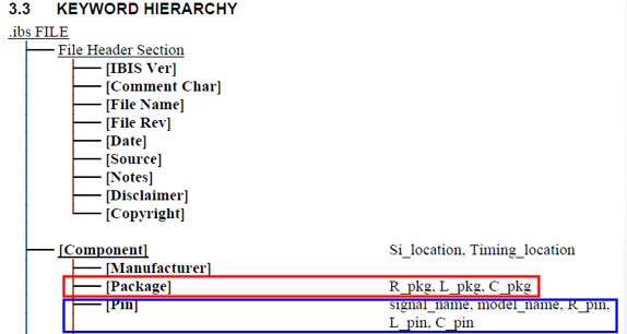
From the IBIS spec, we can see two related keywords for this lumped model representations: [Package] and [Pin]
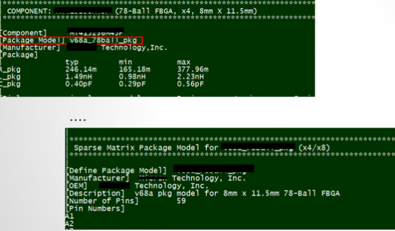
To be more specific, please see this example model:

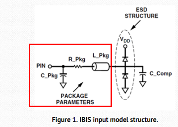
These values represent the parasitic structures as shown below:
This is the simplest, yet least accurate, method to describe the package information. While the [Package] keyword and data is required, parasitic portion of the [Pin] keyword is optional. When both are present, those in the [Pin] section will superseded (i.e. override) values defined in the [Package] section. Thus, a model maker can use [Pin] keyword to introduce pin specific lumped parasitics while using [Package] keyword for general or default values.
Package as a distributed model inside an IBIS file:
A more comprehensive (distributed) package model may be introduced into an IBIS file and model using the [Package Model] and [Defined Package Model] keywords:

Using this method, the component declares the name of a package model it is using (thus the value of the [Package Model] is simply a model name string), and the detailed contents of this package model is defined as a separated section using top-level keyword, [Define Package Model] inside the same IBIS file (usually toward the end of the file, after all [Component] descriptions):
What’s in side the defined package model? Since it’s a “distributed” model and belongs to a component, terminals mapped to a component’s pins are there and so are frequency dependent R/L/G/C matrices etc. The dimension of the matrices is equivalent to the number of pins mapped. With that said, a S-parameter format is not supported here. To use a S-parameter as a package model, one must use either of the remaining two methods to be described below.
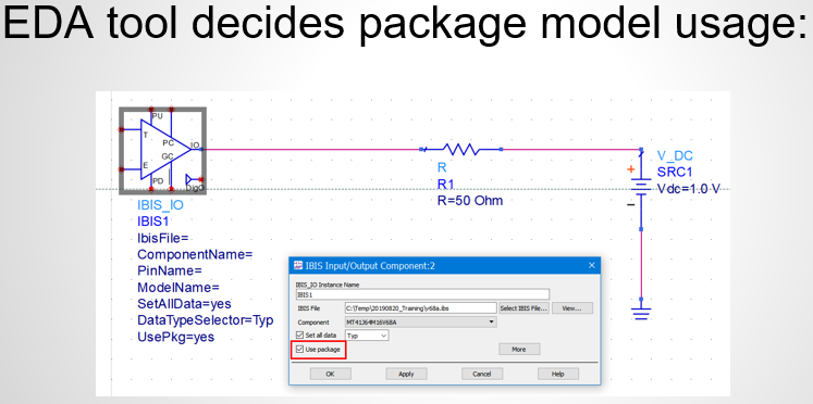
As mentioned earlier, an IBIS file or an IBIS model which has package model info. is just serving as a place holder. Package model’s effects or behaviors are not included in an IBIS model’s IV/VT/IT table data. Simulator has the responsibility to combine these two together… either when computing switching coefficients for lumped model version or “stamping” extra elements into nodal matrices for a distributed one. This also means that different EDA tool may have different methods, syntax or GUIs to introduce package model’s data:
Use ICM as a separated file for package model outside an IBIS file:
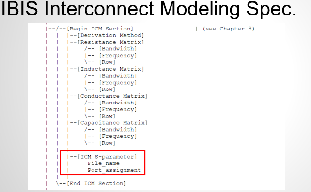
The ICM (IBIS interconnect modeling) spec. is a separated “top-level” spec. document similar to an IBIS spec. So to learn more about it, one has to read the through ICM spec. document
While it’s more or less similar to the [Defined Package Model] mentioned earlier in terms of R/L/G/C frequency dependent matrices etc, it has one unique strength in particular that it supports S-parameter:
So if your extraction tool can only produce S-paramter format, then ICM is the way to go. The table below lists the comparison of different interconnect model format: (PKG is the defined package model)

Use general circuit description for package model outside an IBIS file:
Last but not least… one may also introduce package model contents using a non IBIS/ICM specific format. For example, a model maker may provide a spice .subckt representing the package model (converted from frequency data using tool like broadband Spice or IDEM work etc, can have further hierarchy) or a simple S-parameter. The connectivity should be documented in the simulation guide or usage manual of the IBIS model. It’s the end user’s responsibility to put this as one of the stages in simulation topology. For example, Intel’s platform design guide use such method for an ICH package model:
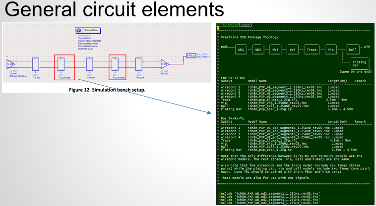
There are pros and cons for this approach: a model user may have more work to have package effects introduced. On the other hand, this method has best compatibility… it does not require supports of a specific IBIS/ICM version in the simulator used, and it also allows probing or sweeping internals inside the package model for debugging or optimization purpose.