In our SPIBPro’s Q3’19 update, we added some new enhancements regarding buffer overclocking handling. While the technical details of these capabilities are reserved only for our customers, the general problem statements and solutions are, nevertheless, worth sharing. This short post will cover this buffer overclocking topic and also serve as a future reference for our customers.
Some of the pictures used here are from previous IBIS summit’s presentations. User may find references to these slides toward the end of this post.
What is buffer overclocking:
We all know that the frequency is equivalent to the 1.0 / period. When an IBIS model is used, the minimal/shortest time period is equivalent to the summation of complete rising and falling transition given by the VT data table:
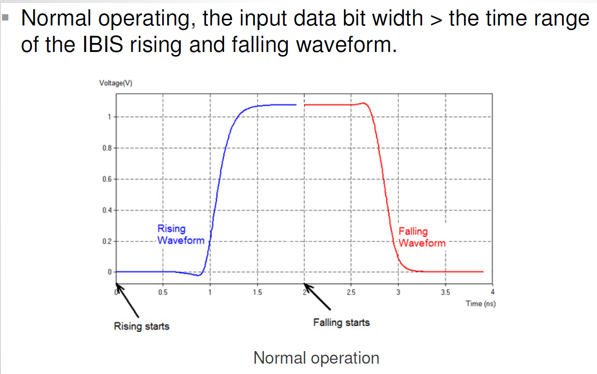
This “shortest” possible time span. thus dictates the highest possible operating frequency. When an input stimulus exceeds this frequency, then this buffer is being overclocked. An overclocked buffer will not have sufficient time to complete either rising, falling or both transitions. As a results, before it’s pad can reach steady state (indicated by the green curve below), it has to make transition toward the other direction again. The outcome of this situation is that there may be discontinuities, glitches or non-convergence during the simulation.
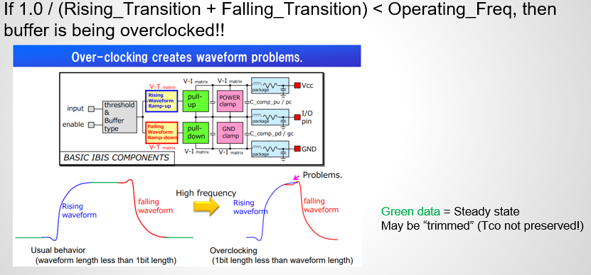
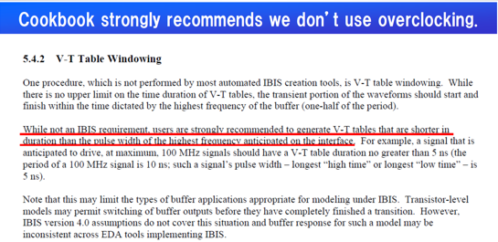
IBIS spec. doesn’t spell out how a simulator should handle in this case. As a result, an overclocked buffer may behave differently across different EDA tools. That’s why in the IBIS cookbook, it’s suggested that a model maker should generate short enough VT duration table so that the buffer can operate fast enough to avoid being overclocked by end user during normal usage. For example, if a USB3 buffer has total VT duration longer than 200ps, then it will definitely be overclocked when user use a normal 5G bps PRBS signal to drive this buffer.
Why buffer overclocking is more problematic in a power-aware model:
To make a buffer’s VT table duration shorter, a common approach is to remove the steady state (flat portion) of the leading and trailing waveform. However, when a power-aware model is being considered, this will present some problems:

The picture above shows both the VT data (rising only here) and IT together. IT is the composite current for DDR DQ-like power-aware model. Since the extracted data of the current portion has pre-driver into account, it’s often the case that there will be “activities” (i.e., non-zero current) long before the voltage at pad starts transition. As a result, the amount of leading steady state can be removed in a power-aware model are often bounded by the IT table. And this limitation is usually very “severe” such that the resulting trimmed model still can’t meet the spec.-required operating frequency.
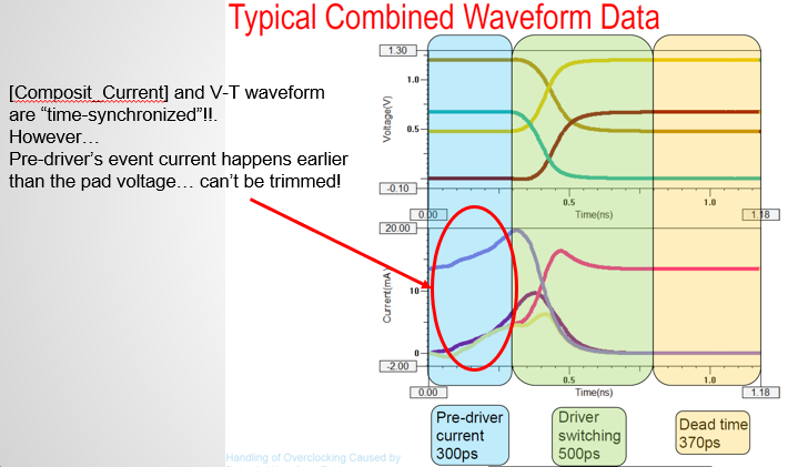
This picture above (from a summit paper) high-light this issue more clearly. It’s also worth mentioning that the “T” of VT and IT table are time synchronized. So one can’t treat these two table separately or shift x-axis time point at will.
Solution to the overclocking issue:
There are several approaches to address this overclocking issue:
- An model user may specify the amount of delay to be trimmed by a simulator, or
- A simulator may apply “windowing” automatically to find the amount of trimming values and apply before simulation, or
- A model maker can create a proper model using approaches to be mentioned in sections below.
The first approach is not only time consuming, but will also easily lead to usage error or non-convergence. The second one may or may not produce desired results. It’s certainly simulator dependent and a model maker/user may not have any control. Nevertheless, the third approach is the preferred one as only the model maker knows how the buffer behaves and exact amount of delay to be removed.
Caveats in model data windowing:
One common mistake of trimming data to avoid overclocking is that different VT tables or IT tables are processed individually. For example, if VT table simulated from one of the fixtures has longer delays than the others, a model maker may tends to remove different amount of delays from different VT tables. Even more severe problem happens when VT and IT are removed independently. All these handling are erroneous due to the following reasons:
- A simulator usually needs to compute “switching coefficients” to apply to IT table data. Their values needs to be calculated from VT tables of different fixture set-ups. Thus trimming different amount from VT tables from different fixtures may cause singularity when solving for switching coefficients.
- That means all [Rising waveform] tables should be trimmed with same value;
- Similarly, all [Falling waveform] tables should be trimmed with same value.
- A buffer’s rising and falling response may be used together in a differential buffer. So if their timing reference are inconsistent, then the P and N terminals will not make transitions at the same time. This may cause “ledges” in the middle of the voltage swings
- That means [Rising waveform] and [Falling waveform] needs to be trimmed with same value
- As mentioned earlier, IT and VT needs to be time synchronized so that gate modulation effect can be properly accounted for.
- That means VT and IT needs to be trimmed with same value.
To summarize, a model maker needs to trim ALL time-dependent table data together with same amount. While trimming trailing time point are relatively easy (just remove those points will do). Trimming from the waveform’s beginning also requires shifting x-axis points to start from t=0. So this is usually better be done with a modeling tool or flow.
Handling of the overclocking:
-
[Initial Delay] keyword:
Due to the limitation of the pre-driver current showing activities much earlier than the pad’s voltage transitions, a simulator can’t do much if both are bundled together in a device model in a simulator. However, if the IT table can be pulled-out from the IBIS device simulation model and be handled as a time-dependent current source, then things will be much easier. That’s why in the IBIS V6.1, two new keywords are introduced for this purpose. They are V-T and I-T for [Initial Delay]:
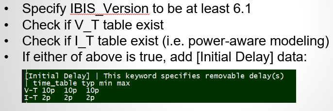
Before using these keyword, one should carefully read the related BIRD document (referenced at the end) and the associated section in the IBIS spec.:
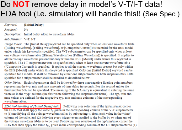
For example, it is the simulator’s responsibilities to remove these specified delay from the “raw” model data before simulation. So a model maker should NOT remove the delay themselves…. simply specify the delay values will do.
That is to say, the modeling process may become two “passes”. At first, once the un-trimmed model data are produced, a maker can use an inspection tool (such as our SPIBPro’s built-in specter) to plot all VTs tables together and measure the common minimal delay to remove. Do the same to all IT table as well.

In the second “pass”, one or both of these two different values are specified under the [Initial Delay] keyword to complete the modeling process.
-
Data trimming and auto-tuning:
For a power-aware model which has IT data, the solution using [Initial Keyword] is the best one. For a traditional, or only voltage related, buffer, a model maker has more choices.
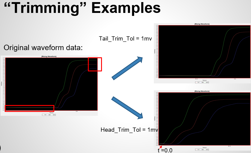
For example, a model maker can start by trimming the trailing steady data. Increment the trimming value or also trim the leading portion until the frequency meets the demands.
This method will alleviate the restrictions of simulator’s support for the [Initial Delay] support… thus an older version of simulator will also work. At the meantime, a caveat worth noting is that the distortion of the model data depends on the amount of data being removed:

So if excessive amount of data is removed, the resulting model may not pass ibis checker (will give DC mismatch violation). In this case, further tuning is needed. Our SPIBPro does perform “AutoTune” automatically during trimming process so a trimmed buffer will almost always error/warning free.
Reference:
The overclocking issue has long been there since early 2000. I remember one of the projects at my earlier career was to address the non-convergence issue in Mentor’s simulator brought by user trimmed model. Interested user may find the following reference useful and worth reading:
