S-Parameter:
In modern channel design, scattering parameters (S-param) is a commonly used to represent passive interconnects. A S-param model is basically a power view (i.e. incidental and reflective) of each “port” under certain reference impedance at various frequencies. So its format is like a frequency dependent matrices each with dimensions equivalent to the square number of ports. In a college text-book, a two port network is usually used to explain these incidental/reflective relationships. Using linear algebra, different form (Z, Y, T, ABCD etc) may also be calculated to be used in different scenarios. One can also cascade two or more S-param. together to form a consolidated S-param model.
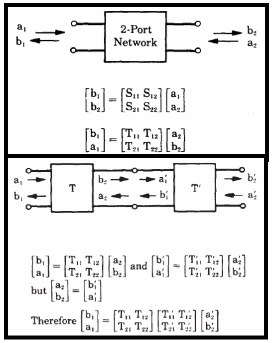
For example, a typical SERDES channel is usually in point-to-point topology. So stages of various interconnects may be cascaded into a single S-parameter.
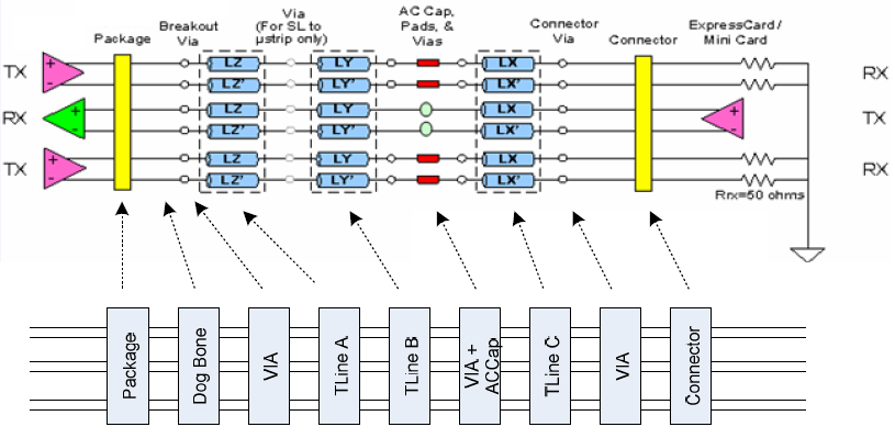
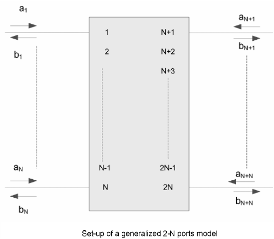
Usually an 3D field solver tool like HFSS/Q3D etc will extract physical design into a S-parameter. For a homogeneous interconnect such as transmission line, 2D/2.5D field solver can be used to extract their RLGC/tabular model data. These RLGC data can easily be converted to corresponding S-parameters. So essentially all these stages’ device model can be in S-param. format and cascaded together. However, when there are more than two ports on each side… such as the schematic shown above, the basic two-port network formulas need to be “generalized” so that plain S/Z/Y/T/ABCD conversion formula can still be applied. That is, the ports needs to be arranged in such a way so that a “generalized 2-N ports” can be formed:
As a S-parameter is passive in nature and represent “power” data, its value or “decay” can be viewed in dB scale and considered as a type of “loss” (compare to 0Hz origin, or 0dB). Depending on the incidental (through-type) or reflective relationship between each ports, different part of S-param may be viewed as “insertion loss (IL)” or “return loss (RL)” from near end (NE) or far-end (FE):
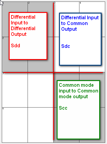
The notation above is for a “single-ended” s-param. To describe a differential channel, a “differential-mode” or “mixed-mode” conversion need to be applied. The forming of “differential” relationship is essentially to subtract certain element in the S-param’s matrix which represents the “return” path or return channel. The resulting S-parameter can thus be used to describe relationship between “modes” such as differential mode or common mode:
As one can see, a s-parameter is so “versatile” in describing interconnect’s properties yet its data is non-intuitive complex numerical matrices, an usual or traditional way of checking a s-param’s quality is to visualize its data and “eye-balling” to correlate to model data from previous design revision or results from different extractors:
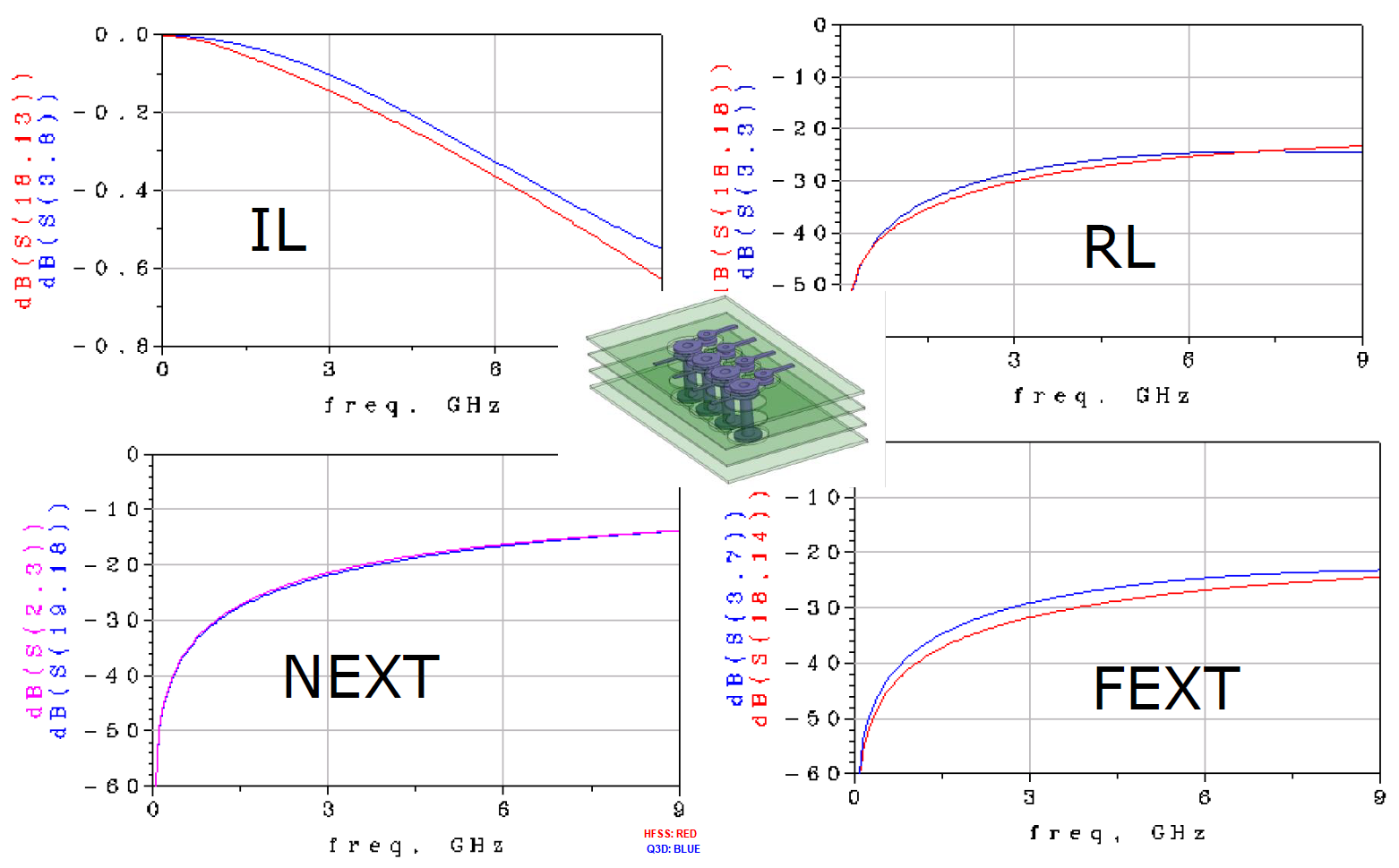
While this method is still useful, the judgement of model’s quality very much depends on one’s experience or tolerance and thus is not very objective. As the data rate becomes higher and interconnect becomes more “coupled” or lossy, new parameters are defined to check a S-parameter’s figure of merits.
Here we list some of important and non interface specific S-parameter checking parameters for reader’s reference. Many of these quality metrics have been incorporated into our SPISPro module for an one stop shop of all the S-param. processing needs.
S-param. check introduced in IEEE 802.3 bj: This spec. defines a “figure of merit” for each interconnect used in a high-speed SERDES (>= 100G) channel. Generic package and motherboard portion are included using behavior models and cascaded with user provided through-type/NEXT/FEXT S-parameter to form a complete and consolidated channel. Then parameters of FFE at the Tx and CTLE+DFE at the Rx are swept to see how good a channel can perform in the best scenarios . A calculated “COM” (channel operating margin” value is then calculated to represent this channel’s potential. COM’s value is significantly affected by cascaded S-param’s parameters listed below:
- ILFit: Insertion loss fit
The inductive and capacitive properties of a channel will introduce frequency dependent loss. To avoid signal distortion, it is usually desired to have a linear relationship between frequency and the channel losses such as well-behaved example below:
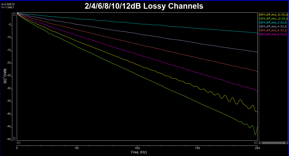
However, due to impedance mismatch and multiple reflections, such linear dependency may not be possible. Thus “ripples” may exist which in terms introduce the time domain noise and causes degraded final eye height/width. A “fitted-curve” (ILFit, up to half of bandwidth, i.e. Nyquist rate) may be introduced to approximate such insertion loss. Such smoothed curve can be viewed as channel without mutli-reflection and is thus a “best-case” scenario.
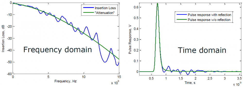
ILfit is usually calculated in a minimized-squared-error (MSE) sense. Pre-defined curve’s order is used and its weighted parameters are then fitted.

- ILD: Insertion loss deviation
Once an ILfit is calculated, one can calculate the “difference” between Ithis fitted curve and original data to form the ILD:
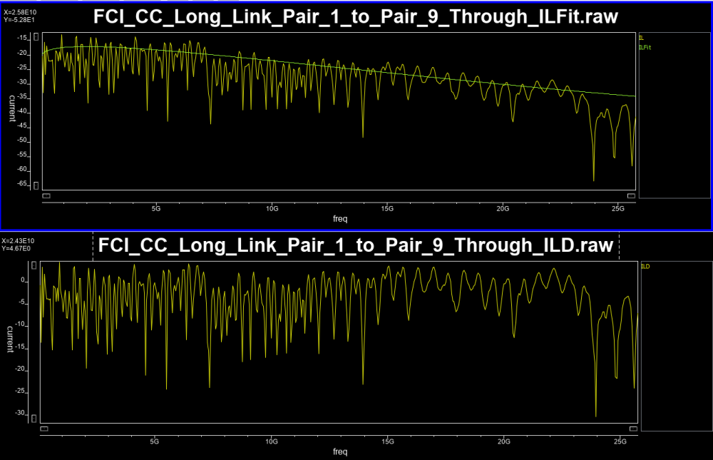
The calculated ILD values can then be further integrated to form a channel’s Figure of merits”:

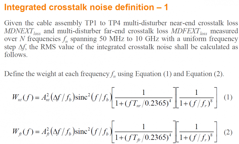
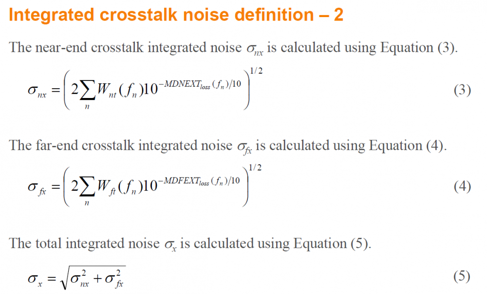
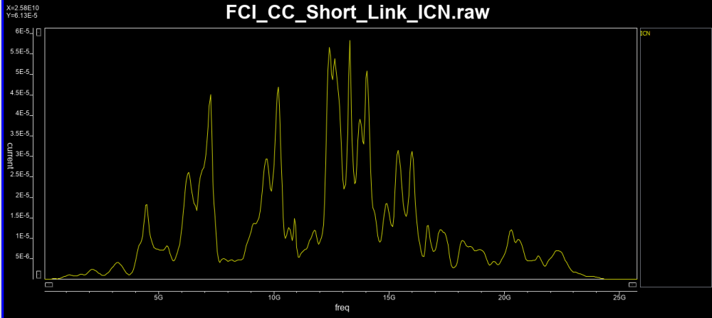
- ICN/ICF: Integrated NE/FE cross-talk noise
These are calculated RMS values integrated (summed) over a frequency range. The integrated value represents impact due to both near-end and far-end crosstalk:
- ICR: Insertion loss to cross-talk ratio
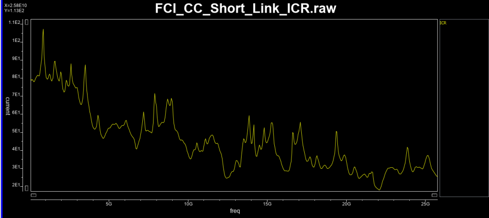
This value compares channel performance’s impact due to insertion loss vs cross-talk.

- COM: Channel operating margin
The amplitude resulting from single-bit-response (SBR) can be separated based on the signal and losses due to crosstalk, insertion loss etc. With equalization at both Tx and Rx side both being taken into account, the best case value will eventually be summarized as an indicator, “COM” for the channel performance’s comparison.

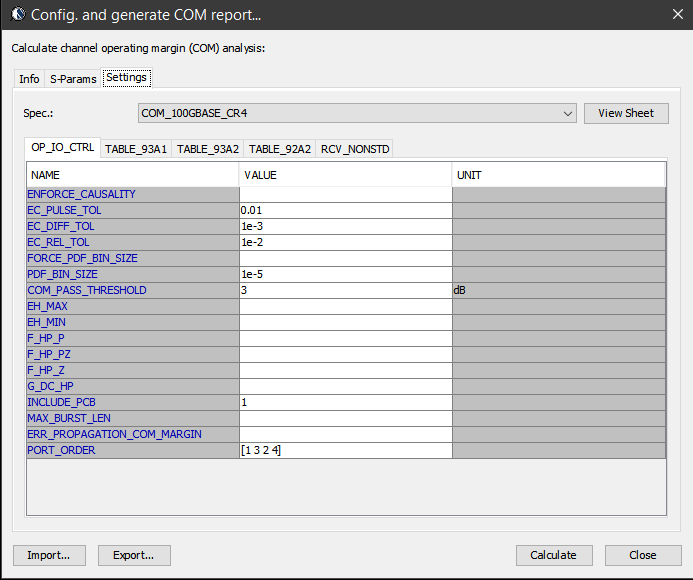
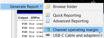
S-param check and parameters defined in COM methodologies has profound impact. It not only sets an example for other interfaces (e.g. USB-C, discussed below) to check their interconnect model, but also provides a meaningful correlation between different S-param’s deviation toward its final eye impact. Details about these calculation can be found in 802.3bj spec.. SPISim’s SPro integrated COM as part of the S-param reporting flow as shown in various plots above and screen shots below:


S-param. check introduced in USB-C Cable/Connector:
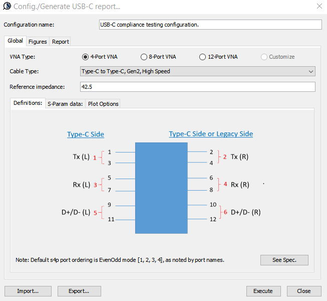
USB Type C (USB 3.1) spec. was published in 2014. Not only does it increase the signaling speed from previous gen. to be 10Gbps, it also provides power charging capability, has a smaller connector form factor and has non-directional connectivity. As this spec. is back-ward compatible, both legacy and low-speed USB connectivity are also supported. As such, there are many different scenarios, coupled with different VNA capabilities to be considered:
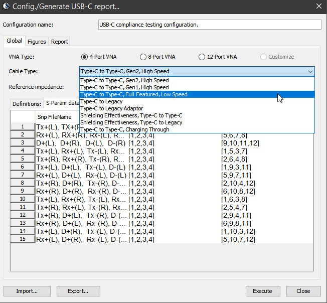
However, the main check (ILD/IMR etc) in USB-C is more or less similar to those used in COM methodology. Nevertheless, there are still minor difference in terms of implementation such as how insertion loss should be fitted and weighted…. as discussed below. In addition, since there are different pairs of traces (e.g. SS, D+/D- etc) in the cable/connector, dedicated checks between signals are also included. Essentially they are calculation applied toward specific S-parameter matrix elements corresponding to the incidental/reflective behaviors between those traces/ports.
- ILfitNq: Insertion loss fit at Nyquist rate
COM methodology in 802.3bj spec. spells out what the fitting formula should be used. However, this is not the case for USB-C. In a reference materials for the USB-C dev. forum’s tool, Interpar, it suggests a different formula as shown below should be used:

In addition, a “weighting” function is suggested to downplay the deviation at the high-frequency portion:

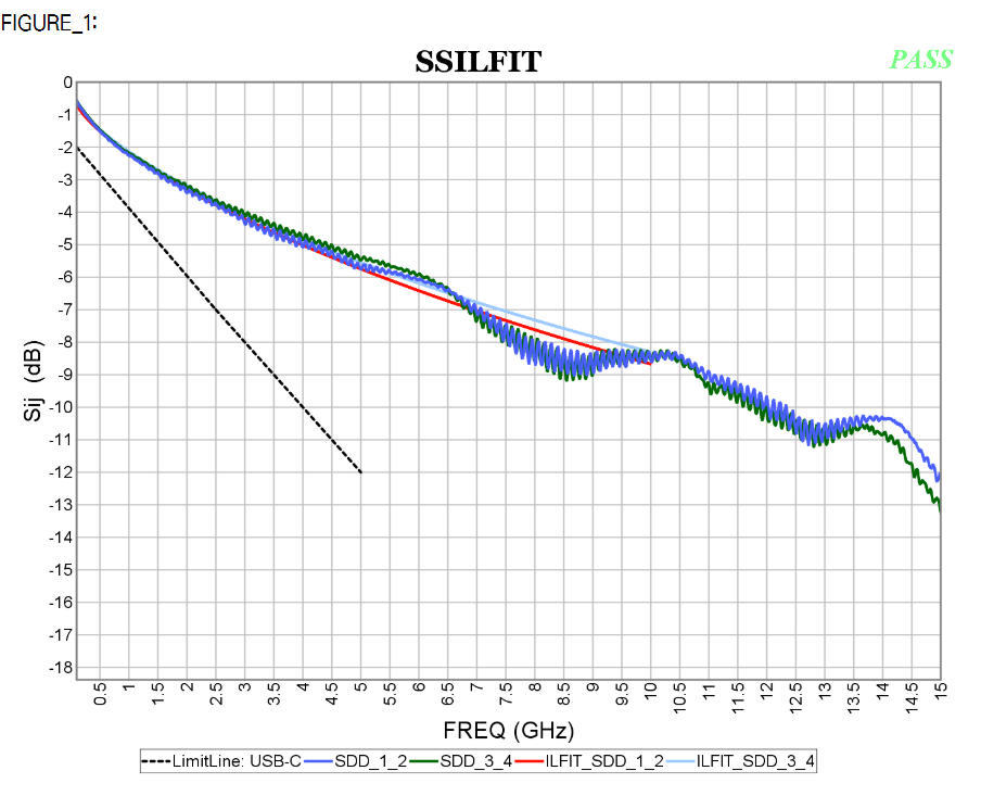
The checking of the IL_Fit/ILD relies more on frequency dependent spec. lines as well up to the Nyquist rate. A “Pass”/”Fail” indicator is then calculated against these spec. line.
- IMR: Integrated multi-reflection
The deviation part (ILD) has been separated to form its own figure of merit using formula shown below:
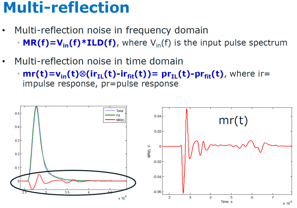
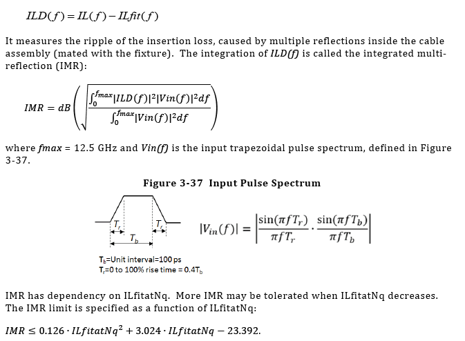
Resulting IMR values are super-speed pair (SS) specific:
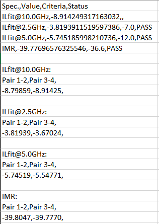
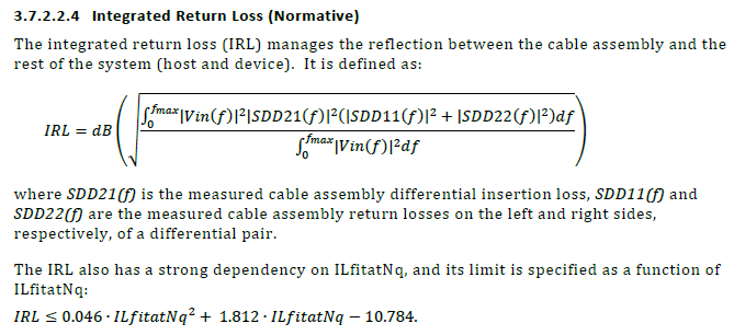
- IRL: Integrated return loss
This is a metric dedicated for return loss check:
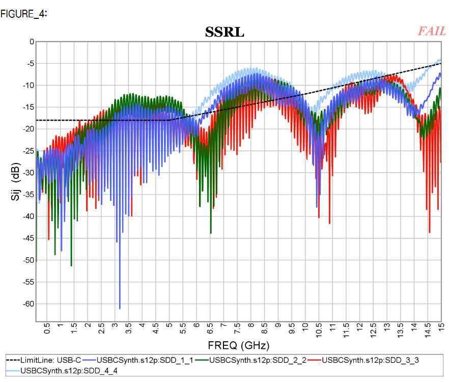
- INEXT/IFEXT: Integrated NEXT/FEXT noise
Similarly, there are metric dedicated for cross talk check and spec-lines:
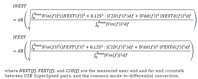
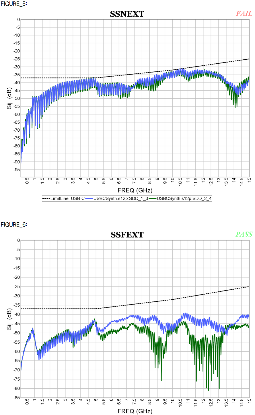
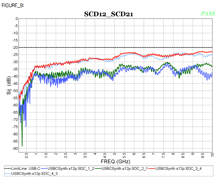
- Others: other signal specific check can be performed by simply configuring and plotting specific matrix elements within certain frequencies ranges then compare with defined spec. lines. Example of differential-to-common mode conversion is shown below.


Both COM and USB-C S-param methodologies are parts of our SPro’s reporting flow:
S-param check introduced in IEEE P370:
IEEE P370 committee’s objective is to define fixture design as well as data quality metric standard for high speed interconnects. A good overview article is available at the signal integrity journal linked [HERE] The P370 WG3, which us SPISim took part in, focuses on S-parameter’s various quality metric (QM):
- PQM: S/Y-Passivity quality metric
- RQM: Reciprocal/symmetry quality metric
- CQM: Causality quality metric
- EQM: Even-Odd quality metric
Previously, we have written a post [LINKED HERE] detailing how these metrics are calculated. Interested readers may also wait for upcoming P370 spec. for the details. One thing to note is that regardless it’s COM, USB-C or channel simulation like those involved IBIS-AMI models, high-quality interconnect/S-param model is usually required as it will significantly impact the resulting impulse response or pulse/single-bit response. When convolving these time-domain responses many times to obtain final PDF/CDR for BER, any initial imperfection in the S-param model will be “amplified” and cause end results’ error. As such, in both COM and USB-C’s flow, the cascaded or user measured S-param have always been checked and adjusted particularly in the aspects of passivity and causality. They are done particularly at the low (toward DC) and high frequency (trailing tails) region. Separated procedures have been applied to extrapolate for a DC point by using first several data points then fit with “theoretical” good behavior model equation to make sure DC response is correct. These details are not even mentioned in the 802.3/USB-C spec…. one must bite the bullet and study to their reference implementation (e.g. matlab scripts) to find such procedure’s existence. Without this auto fixing, calculated COM/Spec. parameters will not match those produced by reference script or InterPar forum tool.


Hi, Thank you for your article.
In your example, what is the DER0 or SER for which you calculate the COM? What is the meaning of COM=0dB and COM=3dB?
Thank you
DER_0 is the BER threshold value at which noise are calculated. As COM an indicator of signal to noise ratio, i.e. A_s / A_n, DER_0 is where A_n will be calculated. COM = 0dB means A_s (signal) = A_n (noise). COM = 3dB means signal is much stronger than noise.
COM’s matlab script is publicly available at https://www.ieee802.org/3/ck/public/tools/index.html, interested reader may download and read it to find how these values are used for COM.