Preface:
We SPISim recently developed and released free web apps for various channel analysis tasks [Click HERE for overview]. While their product page each gives good descriptions and demo about what each tool can do individually, we think it will also be beneficial to put them all together in one flow so that user may have better picture about our ideas behind these developments. Thus this post is written for dual purposes: First we would like to explain how a channel analysis is usually performed. Secondly we want to show how one can perform such process using apps even directly from the web browser. Just for comparison, creating AMI models and license for this type of simulator usually costs tens of thousands of dollars up front. Now it can be done for free!
The big picture:

[Fig. 1, A SERDES system]
Let’s use a SERDES system, shown in Fig. 1 above, as an example. For other interface’s such as DDR, please see our previous blog post for considerations about similar application.
A SERDES system uses a point-to-point topology. In Fig. 1, the middle block enclosed in blue represents the channel. It mainly contains passive interconnect such as package, transmission line, vias, connectors or even cable. However, the channel may also include active components such as Tx and Rx devices. These active components are usually represented by IBIS or spice models. Alternatively, we can pull these active components out from the channel and “merge” them into the EQ as “analog front end” stages. In that case, the channel become pure passive. One of the reasons why one may want to do it this way may be either that the IBIS models are not be ready, or there are no simulators available to have them included as part of the simulation. This is usually the case when a free spice simulator is used as none of them that I am aware of supports IBIS out of the box. In general, unless analog front end AMI models and a pure passive channel, represented as a S-parameter, are used together for the analysis, the active devices do need to be part of the channel characterization in order to obtain accurate time domain response.
The next step is to obtain or generate AMI models for each Tx and Rx EQ circuits. Interested reader may refer to several posts we have written about possible software architecture and methodologies.
Regarding the channel analysis process, a simulator will first convert the characterized channel in s-param, or step response into impulse response first, then depending on the simulation mode being specified, this response or convoluted bit sequence will be fed into Tx and Rx respectively to obtain the overall response. For LTI system, a permutation process will be performed for all possible bit combinations to calculate the PDF of each sampling point statistically, then integrate to obtain the CDF and thus create a bath tub plot. For a NLTV system, bit-by-bit waveform is accumulated and overlapped to plot the eye and BER may be extrapolated from there. While not mentioned here and also not yet implemented, various jitter and noise components are also important when creating the stimulus or calculating final results.
Following the analysis procedure detailed on Section 10.2 of IBIS spec, to summarize them briefly, a channel analysis includes three tasks: channel characterization, EQ model creation and putting them all together for channel simulation.
Task 1. Channel Characterization:
The first step of channel analysis is to characterize the channel, the blue block of Fig. 1, in order to obtain is time domain response. Even with active Tx/Rx front end being involved, the assumption here is that the characterized response will be linear time invariant (LTI). With a LTI input, a channel simulator can either perform statistical analysis if other EQ components are also LTI, or it can have the impulse convolved with PRBS bit sequence to generate full time domain waveform, finally procees to process with NLTV EQ components to get the final time domain waveform for further eye analysis.
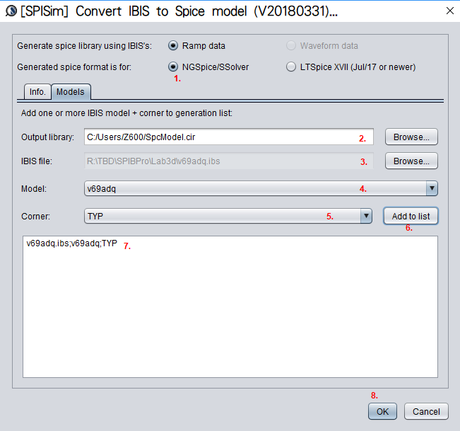
If the passive channel is from post-layout, then user will need to use other 3D extraction tool to obtain the interconnect’s s-parameter. Devil’s details here will then include making sure the S-parameter is in good qualities such as being passive, causal, symmetric and asympotic etc. Also depending on the simulator, converting the single ended s-parameter to mixed-mode/differential one may also be needed. On the other hand, for pre-layout case, user will then first obtain or generate each component’s simulation model. Assuming what user have here are Tx and Rx IBIS model, transmission line and other R/L/C based behavioral models for package, via and connectors, then first one can use our [SPISim_IBIS web app] to convert those IBIS model into free simulator compatible spice subcircuits:
Then head over to LTSpice, offered by Analog device, to download and install the free simulator.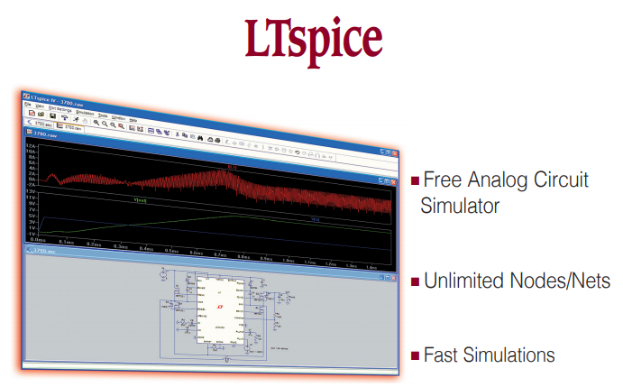
Either create schematic or a text netlist of the channel them perform a transient simulation to get its step response. The output will be a raw file in compressed format which can be viewed either in place in LTSpice or use SPISim’s free SPILite: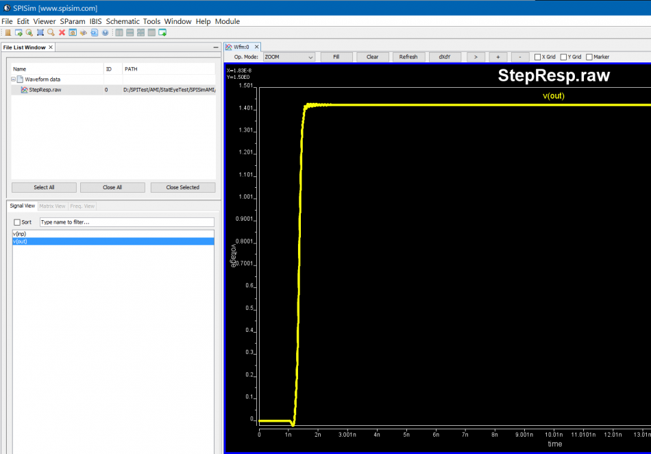
Task 2. Tx/Rx EQ Modeling:
If no EQ circuit is involved, then user can simply tinker the circuit/simulation settings completed in task 1 to perform conventional time domain based SI analysis. The reason stat-eye like channel analysis comes to play is because EQ circuits (represented in green block for Tx EQ and orange block for Rx EQ in Fig. 1) are involved to open the eyes and many more bits need to be “simulated” to obtain/extrapolate low BER, thus can’t be done easily using nodal based spice simulator as it will simply take too much time. EQ circuits can come in different models such as behavioral, spice or AMI, with AMI being the common denominator supported by almost all channel analysis tools from different vendors. Thus in the second task, we need to generate IBIS-AMI models for Tx and Rx EQ.
IBIS-AMI modeling usually involves C/C++ coding or compilation into .dll/.so if starting from scratch. However, user may use [SPISim_AMI web app] to generate AMI models instantly without going through those steps: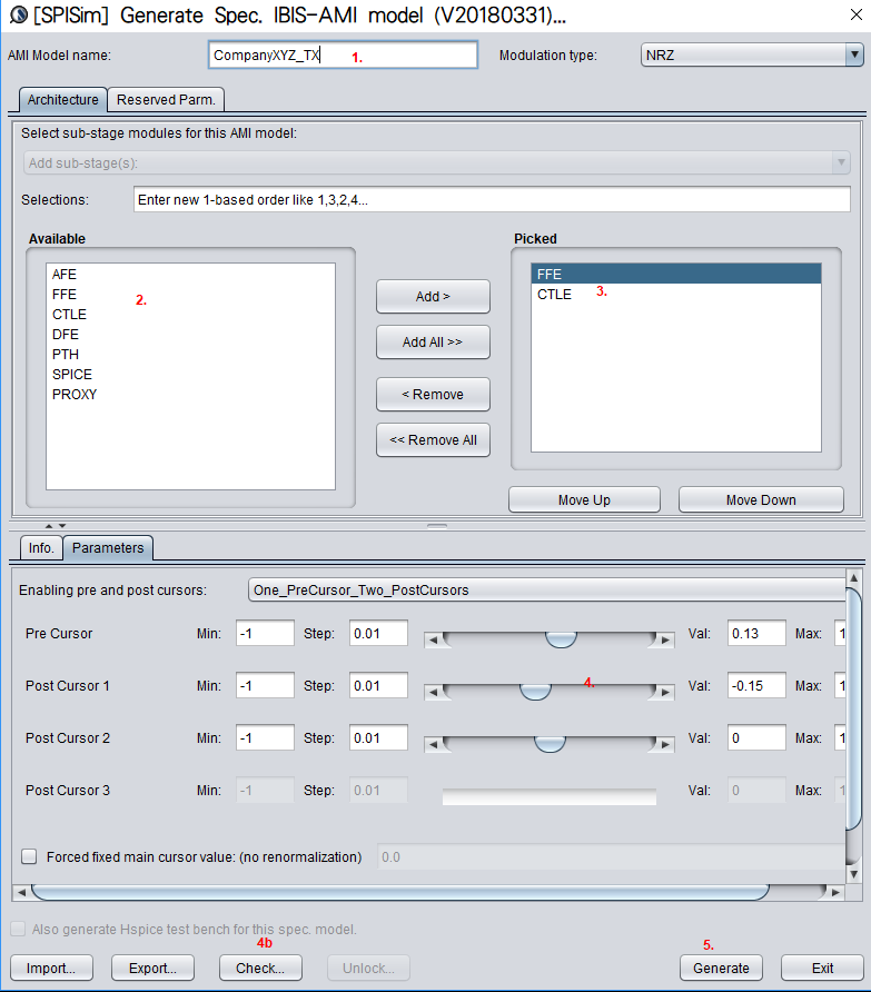
Test driving the model and view its response in place to verify the model’s parameters meet the performance needs: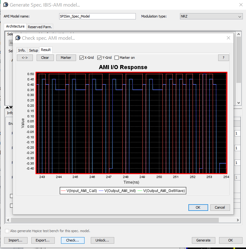
Then click “Generate” button and the AMI model will be generated instantly. If cross platform models are desired, use [SPILite] instead and all Windows 64, Windows 32 and Linux 64 models will be generated in one shot.
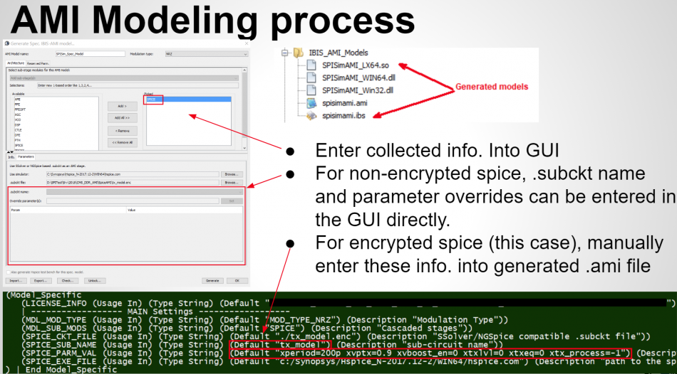
At the beginning of this section, we mentioned that the EQ model can also be in the form of spice circuit, whether encrypted or not. In that case, its detailed behaviors will not be able to be described exactly by template based or pre-defined models. However, a spice wrapper AMI model supported by SPILite can still be used, it will make this spice model “AMI compatible” and can be used in other channel simulators. User’s licensed/installed simulator will be called during the channel simulator.
Task 3. Channel analysis:
With both Tx/Rx EQ models plus channel response being ready, we can then perform the StatEye based channel analysis using [SPISim_Link web app]:
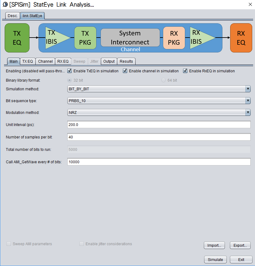
Detailed usage about this tool is demonstrated in a video on its product page. Basically, user can specify the generated AMI models in the “Tx EQ” and “Rx EQ” tab respectively, then do the same for the step response waveform to the “channel tab”. Both “statistical” mode and “Bit-by-bit” modes are supported here, yet if NLTV EQ such as DFE is used in part of the receiver, then “statistical” model can not be performed. With these set-up ready, a “Simulate” click will show the results in place within seconds:
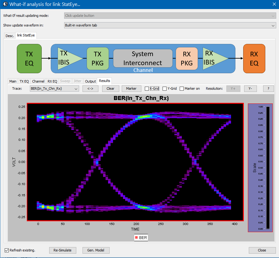
The bath tub curve representing the CDF is also ready for inspection/eye measurement: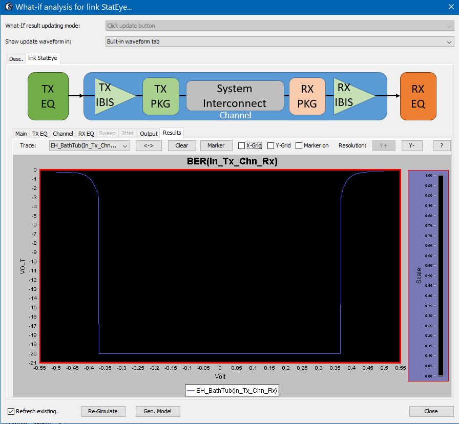
Alternatively, task 1 and 2 are also directly supported in the SPISim_LINK function alone so user may choose to experiment with different settings and see their response first before generating corresponding AMI model. For example, a simple change of post-tap value in Tx can be done in the UI: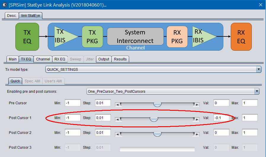
Then the re-simulation will quickly show its effect in resulting eye: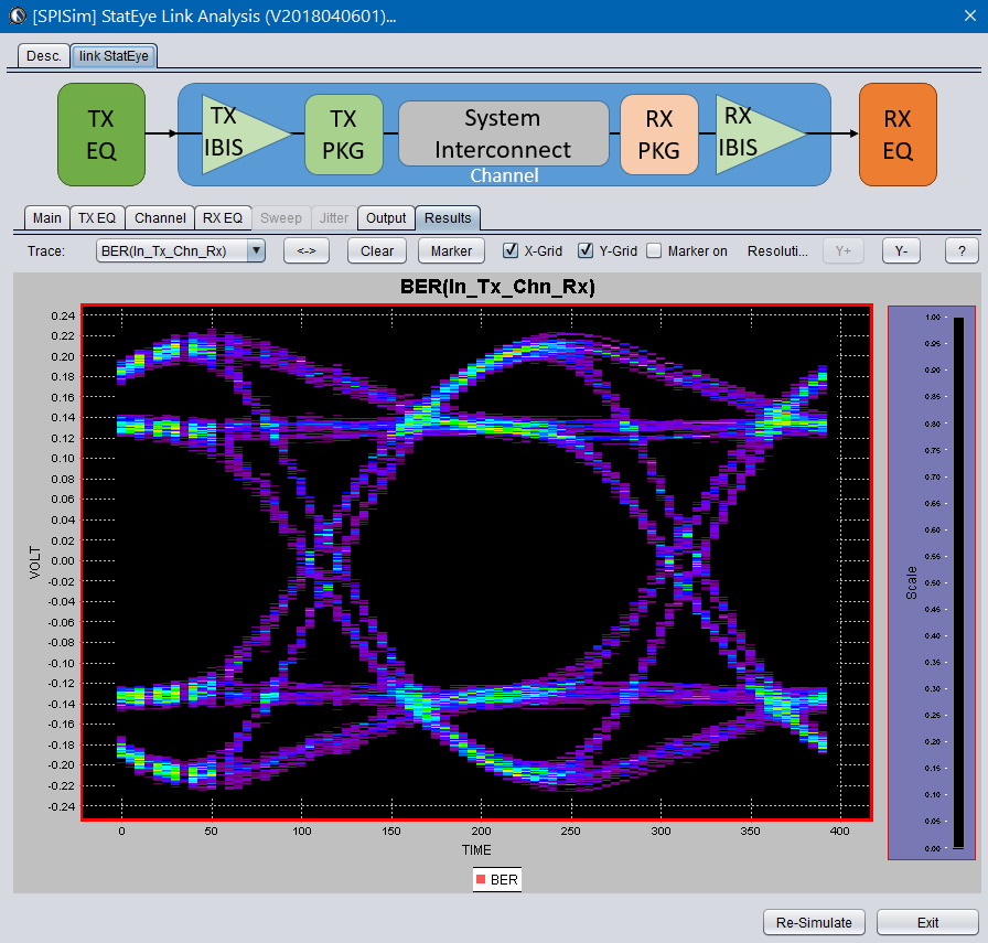
For a system developer, he/she may obtain corresponding AMI models from their IC vendors and follow the same process to give these model a try. For an IC vendor, the AMI model generated here will also be compatible with other vendor’s tool and you may provide these models to your system clients before committing to perpetual version of the model.
Here you have it…. an economic yet efficient channel analysis which can be done directly through the web has been enabled for your design needs without any cost!

