Preface:
At the DesignCon IBIS summit this year, the second half of the meeting focused on the trend and possible approaches for equalization modeling for DDR interface. For the past several years, IBIS-AMI modeling and stat-eye like link analysis have been applied widely and successfully on the SERDES interfaces. DDR, on the other hand, didn’t consider EQ much until recent DDR4 3200 or faster or upcoming DDR5/DDR6 standard. Whether AMI like model and SERDES like flow can be applicable to DDR are still topics of discussion, as the AMI spec itself still doesn’t support DDR properly yet. Nevertheless, the trend indicates that EQ model being part of the DDR simulation will be inevitable.
At the summit, representatives from EDA vendors focusing on AMI and VHDL based approaches and a DDR manufacturer have shared their studies. Interested reader may find related presentation at the IBIS website. Following up these discussion, we at SPISim also performed several experiments of AMI on DDR. In this blog post, we would like to share some of the considerations on this topic as well.
Some major differences between SERDES vs DDR:
There are several major differences between SERDES and DDR interfaces which will affect how EQ models being used as part of the simulation:
- Point-to-point vs Multi-Drop:

A SERDES channel is point-to-point, as shown above. Signals started from a TX propagate through the channel are received by one RX. This Tx-Rx connection may be cascaded in several stages with repeater being used in the middle. A repeater itself contains a Rx and Tx. Repeater may be required as SERDES interfaces may extend very long…from controller to the edge of the board and beyond to connect to external devices (USB, SATA etc). Nevertheless, a SERDES channel looks like a single long “chain”. Thus the nature of the SEDES is “long” and “lossy”.

DDR, on the other hand, is multi-dropped by nature. There is usually one controller on board but several “DIMM”s connections on the other ends. For example, a typical laptop has two SO-DIMMs at least which has combinations of being soldered on board or plug-able through memory sockets. The desktop or server board will have more DIMMs to allow more installed memory. Depending on it’s dual channel, 3-channel or quad-channel etc, they may come in pairs of 2, 3 or 4 respectively. These memory modules usually do not reside too far away from the controller in order to avoid latency, thus no repeater mechanism is needed. The DDR’s topology presents a “short” yet “reflective” nature due to the impedance change at branch points and different termination within each DIMM modules.
- Differential vs Single-ended, Embedded clock vs source synchronous:
SERDES interface are differential, that means they are more immune to noises such as voltage droop or ground bounces, as both P and N signals are susceptible to the same effect so the overall noise is cancelled out. That’s why power-aware models starting from IBIS V5.1 are rarely needed for SERDES. DDR, on the other hand, has many single-ended signals. All the DQ byte lanes are singled-ended so power noise is of a major concern.
Another architecture difference is clocking mechanism. SERDES uses embedded clock so clock signals need to be recovered at Rx from encoded bit-stream (e.g. 8b/10b), which is also part of the transmitted data. A CDR is needed to recover such clock signals and it itself is level sensitive/dependent. DDR uses source synchronous so clock is transmitted separately.
- Operation modes:
For SERDES, there is one direction of signal propagation. Schematic-wise, Tx located at the far left while Rx sit at the far right. Some of the DDR (e.g. DQ) has both read and write modes. Both the controller and memory module can serve as Tx and Rx roles in different modes so the signal is bi-directional. In addition, there are different on-die-termination (ODT) in DDR so the impedance of different DDR module will be different depending on which one is receiving/driving. This “combinatorial” characteristics increases the complexities of EQ optimization as more dimensions need to be swept or analyzed.
Various EQ methods for DDR:
Until recent years, the analysis methods for DDR and non-DDR interfaces are very similar. Topology (either pre-layout or post-layout) are composed or extracted for spice-like analysis in time domain. Worst case pattern may be decided in advanced or just perform long enough simulation to cover sufficient bit sequences. Time based or related performance parameters are than processed and compared against spec. to determine the channel performance.
With the higher bit-rate and low BER requirement, this approach is no longer valid for SERDES. StatEye like convolution based simulation has replaced spice simulation and EQ modeling are also changed to accommodate this analysis requirement. That is why the AMI are getting popular and important these days. We start seeing EQ in DDR4 3200 and will sure to see that being part of upcoming DDR5 and DDR6 etc. So what are the EQ modules we often used in SERDES can be applied to DDR?
- FFE: Feed-forward equalizer. It uses various numbers of taps and weight to eliminate or de-emphasize the signals at different UI. As DDR is quite “reflective”, this EQ method should improve the link performance as it can be used to cancel ISI. The challenging part is that FFE tap weight is pre-defined and may not be adaptive during communication.
The screen-cap below show FFE effect on either single-ended (SE) or differential (DP) signals of different tap location.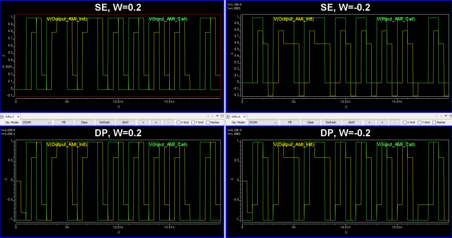
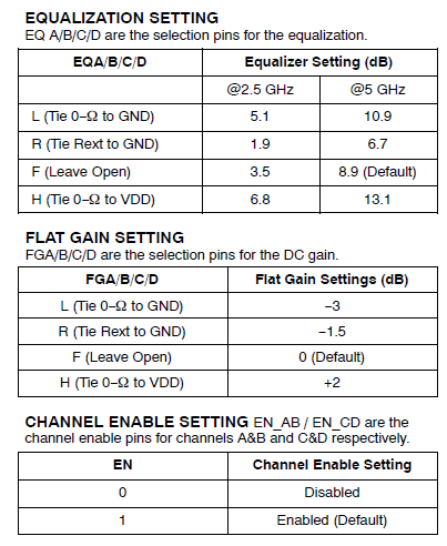
- CTLE: Continuous time linear equalizer. This is usually used to amplify signals of a particular frequency and/or provide DC boost. For example, USB3 operates mainly around 5GHz, thus a CTLE of boost at this frequency can help improving lossy channel for better signal quality. CTLE usually resides at the RX side, its another capabilities is to provide DC boost so that voltage swing received can be amplified to meet the eye requirement. Giving a data sheet:
A set of CTLE curves are often available to boost these performance parameters in frequency domain:
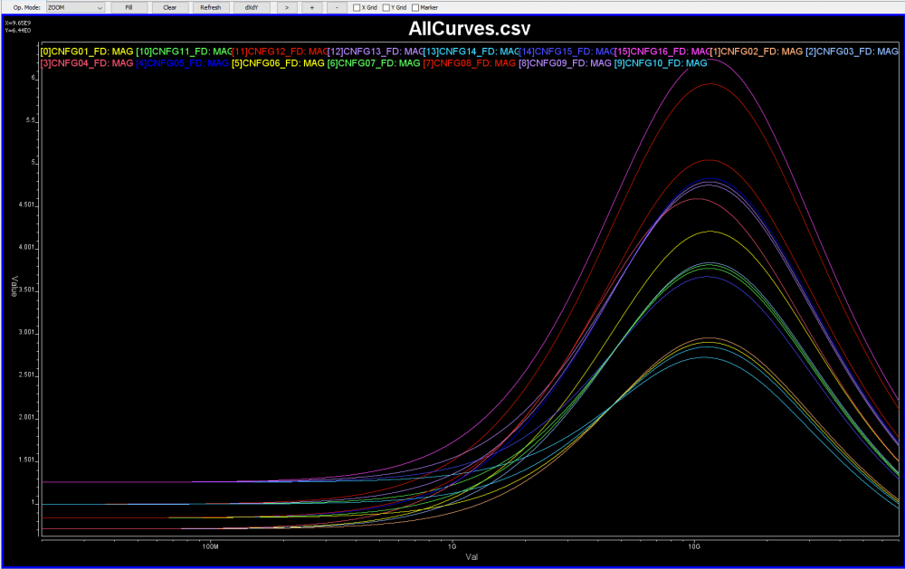
As DDR channel is short but not that lossy, it’s been shown that CTLE is not that useful comparing to its role in SERDES.
- DFE: Decision feedback equalizer. In SERDES, DFE comes with CDR as a DFE needs clock signals to preform “slicing” for tap adaptation:
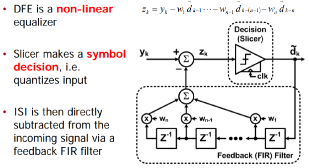
While this is another form of ISI cancellation, it can be applied dynamically based on the link condition. So there is a period before the DFE will “lock-in” with stabled tap weights. For this reason, it has similar effect as FFE for a reflective channel yet may be more versatile. However, the DFE itself is non-linear so it can only perform in bit-by-bit mode. In contract, FFE is a FIR and can be used in both statistical and bit-by-bit mode simulation.
As both FFE and DFE show similar effects of ISI cancellation, there may be redundancies if both are used at the same time. Our study validates this assumption in one of the case whose results are shown below:
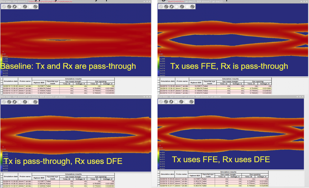
Both FFE and DFE alone will open the closed eye significantly yet when used both together, the results is not much different from only using one of them. If this is the case for most DDR cases, then the important topics is to perform “sweep” efficiently in order to find out number of taps and weights required in either FFE and DFE module used.
Insufficiencies of current AMI spec for DDR:
As of today, IBIS-AMI being applicable to DDR is still questionable. This is because IBIS-AMI so far is SERDES focused and it’s spec. need to be revised before DDR can be covered. Here are some of these shortcomings that we are aware of:
- Step response/RF response:
In the spec, the “statistical” simulation flow describes that a channel’s impulse response is sent into Tx in the AMI_Init call. Practically, such impulse response only exists in theory and is not easily obtainable with circuit simulation. Instead, most link analysis use step response then post-process by taking derivative to obtain the impulse response. The assumption of this approach is that channel’s rising and falling transition are symmetric, which is usually not the case for single ended signals such as DDR. Thus in order to perform StatEye like convolution based link analysis more accurately, one may need to forgo the single impulse based statistical analysis flow but resolving to full sequence based (e.g. PRBS sequence) bit-by-bit flow.
- Clocking:
IBIS spec. assumes the signaling is clock embedded as the only place where clock is mentioned is the function signature of AMI_GetWave:
 The usage of this clock_time is “output” from the AMI model. That is, the (RX) model can optionally recover the clock from the “*wave” array then return the clock data back to circuit simulator. As mentioned previously, DDR is source synchronous so a clock signal is already available outside the “*wave” data. In my opinion, this is an easy change as the spec. can simply indicate that the “clock” data can be bi-directional, meaning that simulator may receive clocks elsewhere then pass its data into the AMI model using this clock_time signature while calling the AMI API. Then the RX’s DFE can make use of the pre-determined clocks to perform slicing and tap adaptation. Nevertheless, this clocking difference has not yet been addressed in the spec. as of today.
- Signaling:
In the IBIS-AMI spec, user will find differential signal being assumed as the description below indicates stimulus is from -0.5 ~ 0.5:
By definition, a LTI EQ model’s transfer function is independent of the inputs being scaled and shifted, thus it basically behaves the same regardless of single-ended (SE) or differential (DP). A NLTV model, like RX DFE, does depend on the proper threshold to determine signal data bits. Thus whether it’s SE or DP does make difference just like whether the encoding scheme is NRZ or PAM4. Besides those descriptions change like shown above, a simulator/link analyzer can theoretically perform signal shift before calling AMI model then restore afterward automatically so that most of the developed AMI model mechanism can still be used. Alternatively, an AMI model can achieve similar effect using a level shifter if the spec. indicates that such adjustment will not be performed by the link simulator.

The waveform shown above is a 3rd party vendor’s link simulator being applied to DDR analysis using IBIS-AMI. As one can see in the left, the channel characterization shows that the voltage swing of the single ended model is 0.4 volt ranging from 0.95 ~ 1.35. However, the waveform sent to IBIS-AMI models has been re-centered around 0.0 so the swing range is -0.2~0.2. Apparently, what the simulator has done is taking the ground based channel characterization result to convolve with differential stimulus required by the spec. This vendor’s simulator then does smartly restore the output from AMI model back to single ended so the final eye presented are shown at correct voltage level.
Other EQ modeling methods:
In this DesignCon IBIS summit, a VHDL/Verilog-A based modeling approach was also presented to show that with such EQ model/mechanism available, the traditional time-based simulation flow can still be used and for DDR, the million bit simulation (thus requires AMI like models) are not necessarily needed. That paper show comparable results such as eye margin etc obtained by this VHDL based model. Personally, I don’t think this result is viable too much beyond that particular study. The reason is that VHDL/Verilog-A as a modeling language has great limitations when being compared to C/C++ based language which AMI uses. This is particularly true in the following aspects:
- Libraries: performing numerical computation in C/C++ is quite routine and many libraries have been developed so very rarely one needs to start from scratch. For example, GNU and LAPACK are both widely used as foundations of C/C++ based numerical analysis. Where are these counter parts in VHDL/Verilog-A? Without these, model development beyond simple sequential programming will be almost impossible or too tedius.
- IP Protection: Compiled C/C++ codes are basically machine codes and can’t be easily de-compiled. This is why AMI is considered as IP protected while IBIS is only abstract to the behavioral level. VHDL/Verilog-A are mostly plain-text based and even when encryption/obfuscation is possible, the model soon becomes vendor simulator specific because only they can decrypt/interpret the scrambled codes. This defeats the purpose of the shareable model.
- Speed/Flexibility: Interpret language will not be as efficient as compiled ones. While whether there is really needs for a compiled language such as C/C++ can be discussed, VHDL/Verilog-A will still be the less likely choices regardless. In my opinion, a possible direction may be language such as Python because it not only is open sourced, but also supports C API and has rich numerical libraries support (NumPy, SciPy)
The discussion above summarizes my understanding and observation of EQ or AMI’s usage for DDR. While the implementation may not necessarily be the same, I believe we can rest assured that EQ will be part of DDR spec to come. Even if it’s not AMI, it will just be built on top of existing modeling methodologies so far just like AMI stands on the shoulder of transitional IBIS.


Pingback: A channel analysis trilogy | SPISim: EDA for Signal Integrity, Power Integrity and Circuit Simulation