
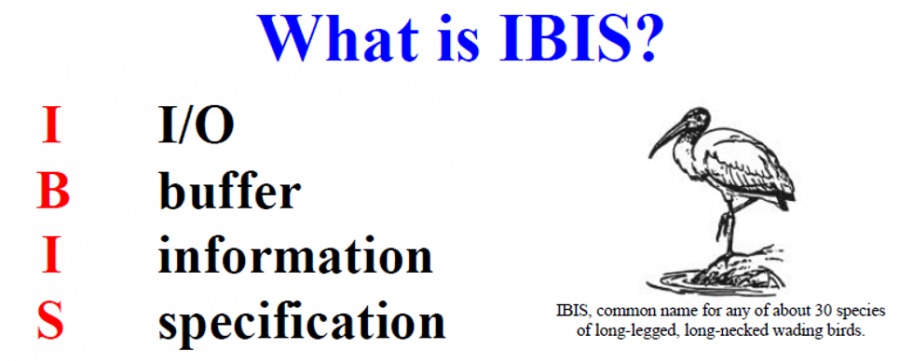
IBIS is short of I/O Buffer Information Specification. The spec. was proposed in early 90’s to promote tool independent I/O models for system level analysis. It’s been evolved since even until this date. It’s now an ANSI standard and are widely supported by different system level EDA vendors, including SPISim.
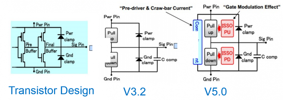
IBIS model is created as a behavoiral model for transistor’s buffer deisgn used in system level analysis. Several milestones and its delta improvements have been listed briefly below:
- Version 3.2, using IV/VT data table to address and meet most signal integrity’s needs.
- Version 4.0, introduces other language such as Verilog-A, VHDL and Berkeley spice as external circuits to address shortcomings of rigid IBIS syntax, which often is not flexible enough to represent behaviors more advanced buffer design.
- Version 5.0 introduces power aware features. By introducing ISSO PU/PD and Composite Current which represents currents drawn from power delivery network (PDN), the voltage droop and ground bounce issues during simultaneous switching can be modeled and analyzed.
- Version 5.1 introduce AMI to account for equalization mechanism which sits transmitter’s analog front end and behind receiver’s buffer output. AMI model is mostly written in C/C++ compiled into .Dll or .so loaded by simulator. This deviation from more high level language such as Verilog-A gave model designers tremendous flexibility in modeling the full EQ + buffer to enable bit-error-rate based analysis. However, it also significantly increase the barriers and difficulties to create a good buffer model.
When talking about the term “IBIS””, one needs to distinguish about IBIS Spec, an IBIS file and a IBIS model. The following list gives simple overview:
- IBIS Spec: Spec. defined by IBIS committee. In addition to the buffer related portion, its general meanings may also include connector spec (ICM, InterConnect modeling Spec). ICM provides standard model format for all electrical interconnects such as cables, connectors, package and printed PCB. Previously, a different spec, EBD… electric board description was used. ICM is to replace EBD.
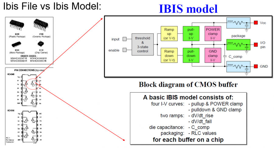
- IBIS File: An IBIS file is like a container of models for an IC or chipset. An IC package usually has many pins, with several buffers inside. Thus an IBIS file usually have manufacturer’s info as part of the headers, followed by different pins, pin names and connected buffers, then detailed various buffer models and their modeling data. An IBIS file may also have package models and AMI statements which points to associated .ami and .dll/.so files for corresponding equalizer portion of the design.
- IBIS Model: An IBIS model is an individual buffer model sits inside the IBIS file. Depending on modeling type and the IBIS version, it may have I/T, V/T, I/V data tables and corresponding operation and loading condition when these model are being excited for modeling. It’s desired the usage of this buffer model should not deviate from the modeling condition too much as the behavior in those range may not cover properly in the constructed model.
IBIS Files vs Models
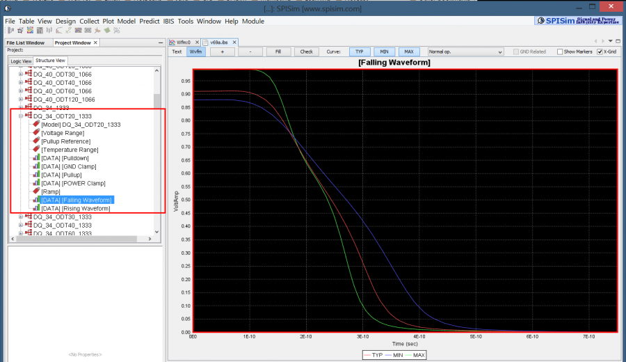
Viewing model data of an IBIS file in SPIBPro