

Optimization for system performance:
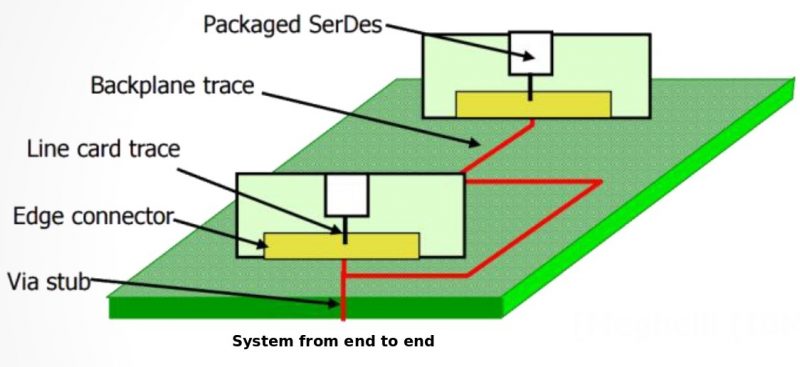
For electrical analysis such as signal integrity, a “system” is usually defined from end to end, i.e. from IO buffers of an IC, going through passive interconnect such as package, traces and vias, then connector or package again down to final receiver. There are many components involved in such a channel. Each of them has their own design parameters, so there are many factors affecting this system’s performance. In addition, there are also different performance matrices, such as eye height, width and timing margin etc. There maybe trade-offs between these performance targets. For example, the largest eye width may not produce the largest eye height, so either one is more preferred than the others or a weighting scheme needs to be used.
 Sources of noise affecting performance:
While the end goal is to maximize desired performances, they are actually affected by several electrical functions in the form of noise sources. We can imagine variables from individual channel components as x1, x2 ~ xn, these noise function g1(x1, x2), g2(x1, x3..) etc are part of performance function f(g1(x), g2(x)…) = f(x1, x2 ~ xn). This partition usually makes connections between variables and the noise response, i.e. x1, x2 to g(x), more meaningful and easier to understand. Not doing so, the big system function f(x) will have all variables lumped together. Another considerations is that many of the variables are orthogonal to each other, so by lumping strongly coupled ones into same g(x) functions, we reduce the efforts required to search for the whole solution space.
In a system, sources of noise can be categorized roughly as the followings:
- Inter-symbol interference (ISI): this is usually caused by signal dispersion along the channel and the reflections due to impedance mismatch. A symbol (lone 1 pulse) starting as a nearly square wave at the driver may end up as a distorted one at the receiver due to this interference with itself.
- Cross channel interference (CCI, or crosstalk): This is caused by inductive and/or capacitive coupling between victim and aggressors, they are mostly dominant at higher frequency and are very material and geometry (relative distance) sensitive. Componentwise, they maybe from on chip source (mainly capacitive) and off chip such as transmission line or vias etc.
- Power supply noise: Different workload of the buffers may affect the terminal supply voltage. For example, when all buffers are driving, current supply may be limited and thus voltage will drop, and the slew rate will change accordingly as well.
- Random noise: This is due to thermal noise (usually Gaussian distribution) or other jitters.
By exploring relations between x and g(x), it will help achieving end goal of optimizing f(x).
Optimization approaches:
Giving so many variables (x1, x2 ~ xn) and either intermediate (g(x)) or final performance (f(x)) functions, how do we find the best xi values such that f(x) will be optimized (either maximize or minimize, by itself or weighted among several f(x)s)?
A channel being designed must have a spec. to meet. Different industry standards such as PCIe GenX, HDMI, SATA, USB, DDR etc each has its own compliance matrices before the designed final product can be certified to use such logo. For a smaller design company or when time to market is a constraint, a designer usually only want to look for “a” solution rather than the best solution. For bigger companies which provide design guides, they may need to do full analysis to make sure even in the worst condition, their product will still functional properly when being used by other companies in their own designs. In addition, perform a “full analysis” usually requires lots of simulations so computing resource available also imposes a constraint. Generally speaking, there are two approaches for system optimization:
- What-if analysis: In this approach, many of the design variables have been set to a “fixed” value and a designer linearly explore impacts of limited remaining variables to the noise function or performance. Since each variable is adjust linearly, it’s not likely global best/worst values can be found this way. On the other hands, this what-if flow has the following benefits:
- Can run with limited computing resource;
- Can find “a” solution more easily and quickly;
- Can help a designer gaining more insights regarding a variable’s impact on the performance, thus help a better design in the future.
- Systematic methods: This approach can be considered as “what-if” analysis in multi-dimensions. Much more variables are taking into account with their respective ranges of values (thus still not “global” strictly speaking). The following steps are then taken to find min/max solutions in such a multi-dimension design spaces. (They will be explained in more details in separate post.)
- Create sampling points:
- Create corresponding test cases:
- Simulate and post-processing:
- Map inputs to outputs:
- Optimize:
- Study non-fitted results:
More on what-if analysis:
What-if analysis explores solution spaces linearly and usually provides instant response/feedback to the designer, so the chosen variables should have dominate impact on performances and the channel setup should be simplified. If only ISI and CCI are considered, one may break the aforementioned channel and lump related variables into the following sections to explore individually:
- Driver: driver’s strength, slew rate, supply voltage, EQ settings
- Interconnect:
- transmission lines: layer stackup and materials Dk/Df, trace width, distances and layout etc
- vias: pad, anti-pad size, barrel width, back-drill etc
- package/connectors: change of reference and reference impedance etc
- Receiver: termination scheme and different terminator values, EQ response and settings etc.
Note that driver/receiver variables here are behavioral already rather than original design parameters such as transistor sizing, doping concentration etc. So a behavioral model like IBIS, AMI etc need to come into play. For interconnects, solving transmission line using 2D/2.5D solver based on their physical and geometrical properties are more feasible, comparing to solving those for 3D structures like vias or even connectors. For these via/connectors, a simplified model may again need to be built and come into play for quick what-if analysis.
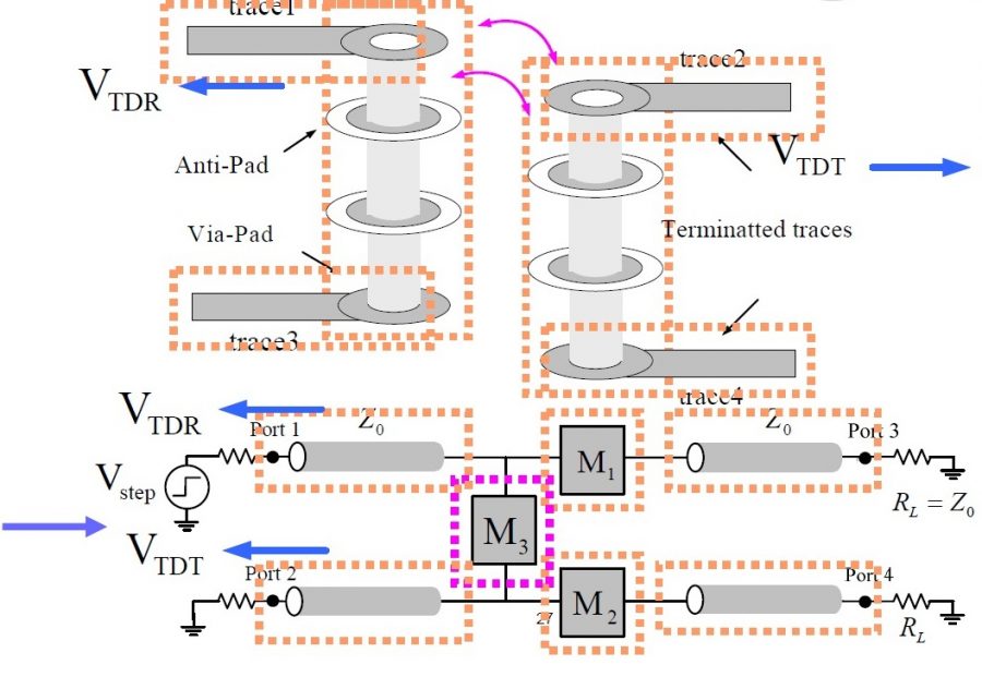
Via model into PI model based on TDR results
The trade-off:
We think the value of a signal/power integrity engineer is very much on his or her insights on the design variables involved and their impacts to system’s performance. Such insights can be obtained from direct what-if analysis and/or detailed study of prediction model constructed via systematic optimization approach. The pitfall of the later one is that, with established flow and design cycle constraints, an engineer may easily become a “simulation engineer”, who just execute the flow and produce report without detailed study or understanding of interaction between different design variables.
SPISim’s support for system optimization:
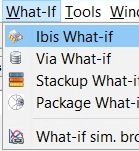
With the spirits mentioned in this post in mind, we have flows for both what-if and systematic approaches. In our XPro module, variables in simplified setup has been categorized in advance to explore their impacts on ISI, CCI and power:
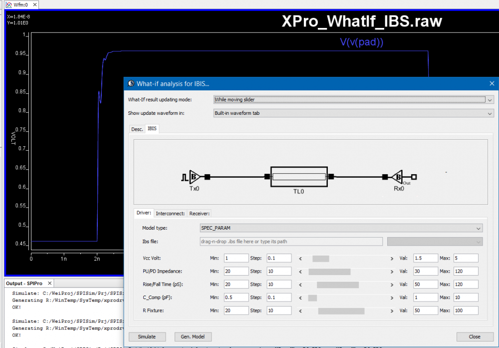
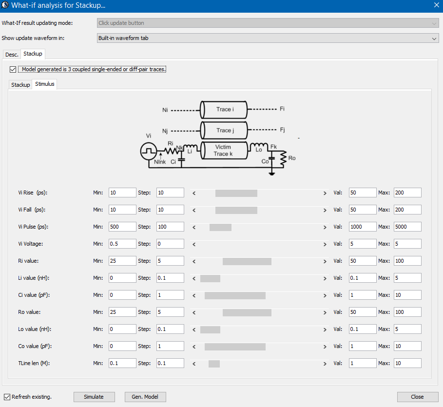
Not only will they provide instant analysis results via built-in simulator, the final model can also be generated in place based on the variables’ values used. These features are not available on may other commercial offerings and will be valuable capabilities to a system engineer.