SPISim’s CPro Overview:
Design Concept:
In pre-layout flow of system level design, a schematic editor allows user to build channel from scratch, assign different models or corners for involved components, and perform simulation or analysis. With post-layout data, the layer stackup, trace width and length, via’s pad-stacks can be translated to corresponding schematic allowing user to fine tune performance, experiment different trace spacing before going back to modify layout data. SPISim’s CPro provide such capabilities to allow user create, view translated, and simulate channel in a simple and integrated GUI.
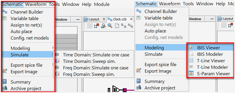
Environment:
CPro is an add-on module in NPro’s main menu. It allows user to create schematics from scratch or from extracted post-layout nets. In addition, CPro integrate closely with other SPISim’s module to provide direct support of IBIS, T-Line and S-parameter modeling and analysis. It actually serves as a design cockpit to manage and control elements, corners and connectivity involved in channel analysis.
Work flow:
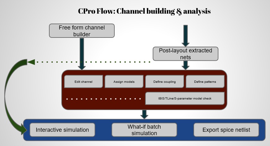
- Create channel schematic from scratch;
- View/experiment schematic extracted from post-layout net;
- Simulate and measure channel performance;
- Perform what-if to sweep model/channel variables for optimum solution.
Create channel schematic from scratch:
Free form schematic editor for channel building
CPro’s component palette focuses on support of system level elements, such as IBIS, transmission lines, vias, s-parameters and sub circuits etc. User only needs to drag-N-drop from palette, make connections with mouse clicks or keyboard short cuts and right click to configure each element’s models or values. Sub-circuit like hierarchical support is included and schematic can be exported/imported easily to an xml-based format.
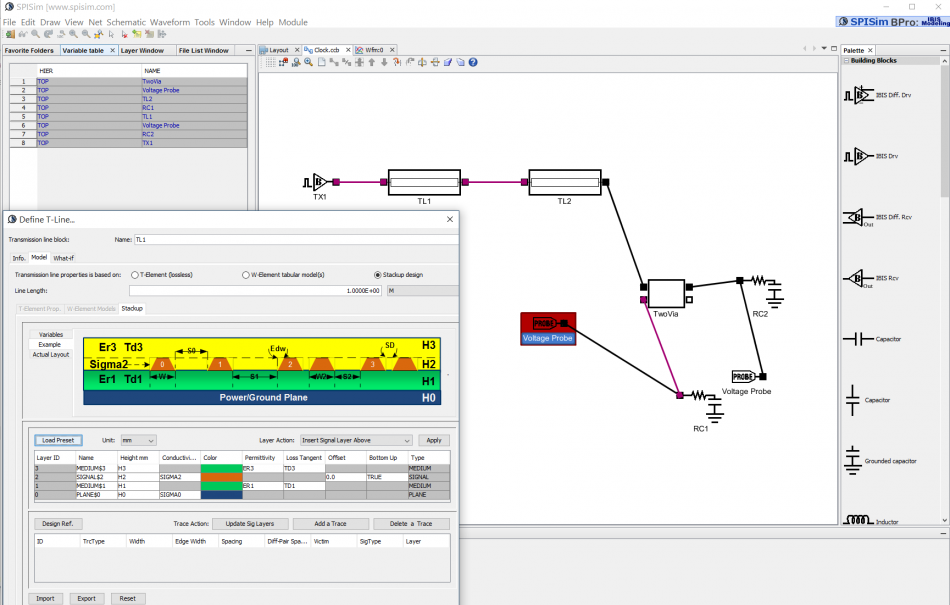
View/experiment schematic extracted from post-layout net:
CPro provide functions to extract selected nets from post-layout module, NPro, into schematics. During design translation, transmission line models will be constructed automatically based on layer stackup, trace width and line length. Element names are preserved to reflect their counterparts in post-layout so user traverse easily and to identify potential problematic region (e.g. for cross talk). Different nets can be coupled together via coupled transmission lines to investigate their cross talk impact. In addition, schematic can also be exported as HSpice compatible netlist for either time-domain or frequency domain analysis.
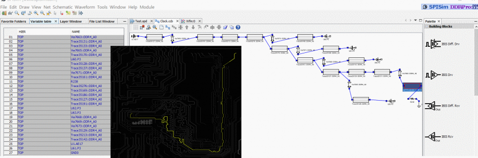
Extracted DDR channel from NPro to CPro
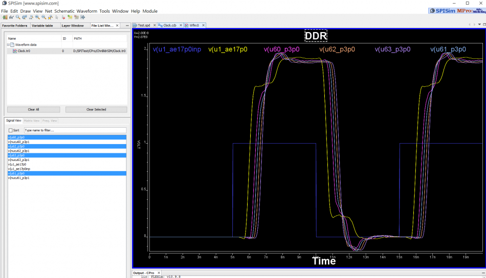
Simulate and measure channel performance:
Once channel schematic, model and stimulus are set-up, user may perform simulation, view results and measure performance directly in CPro’s environment. User can then change different corners or modeling parameters and simulate to see updated results. This interactive process gives designer instant feedback of impact of particular variable on channel performance.
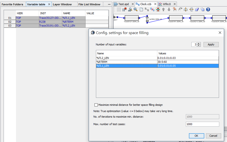
What-if to sweep model/channel variables for optimum solution:
When more than several design variables are involved, linear search of solution via interactive simulation becomes less efficient and one must resort to what-if sweep to identify solution space and optimized configurations. In CPro, all channel elements can have variables defined as part of modeling parameters. These parameters can then be used to define what-if simulation plan. Full factorial, space filling or other (DOE or RSM etc) plan can be defined either directly or via supported MPro module. This what-if simulation plan will then be executed by CPro for sweep simulation. Both time domain (bit-by-bit) and frequency domain (s-parameter extraction for bit-error-rate analysis usint statEye) are supported.