SERDES fundamentals:
Modern high-speed designs usually use either serial or memory interfaces. The former includes PCIe, USB, SATA, MIPI and XAUI (Ethernet) etc while the later typically refers to DDR. So far as serial is concerned, their input and output signaling are usually accomplished by “Serializer” then “DeSerializer”… thus called “SERDES”. A SERDES channel typically starts and ends with Tx and Rx silicon blocks respectively. These blocks include analog front-end portion (usually represented by IBIS) and equalization (represented by AMI). Sitting between Tx and Rx are interconnects… which can be PCBs, cables and connectors or even fiber optics with or without repeaters. SERDES’s signaling usually impose bottleneck which limits the overall performance of a high-speed system.
Traditionally, SI analysis are done in time domain mostly involves running many bits. The rise of high-speed IO demands the performance matrices and spec. to be BER based thus it’s no longer feasible to run time domain analysis for million of bits. On the other hand, the interconnect channel portion is mostly assumed to passive and LTI. The analog-front end portion (IBIS model) are also usually “absorbed” into the passive channel as part of the interconnect. These two remain the same as the before. The needs of “Serializer” and “De-Serializer” results from the fact that equalization are a important part of both Tx and Rx in order to make the eye “open”. It’s the EQ nature of the Tx/Rx and the requirement of running million of bits in a timely manner which demands the new analysis approach (“Statistical”/StatEye analysis) and new models such as IBIS-AMI.
Tx/Rx’s EQ design for a SERDES system is a complex and iterative process. In the floor planning phase, system margins are budgeted so a tentative spec. for either Tx, Rx and channel as well can be defined. Silicon may then be designed to meet this spec. AMI models are finally generated based on the silicon performance. Alternatively, an “ideal” behavior AMI model can be constructed in advance to explore the solution space before committing to silicon spec. The third possibility is that the AMI models can also be built from lab measured silicon data… thus happens at the very end. Finally, a training algorithm may be implemented either in the AMI models, EDA tools or even manually performed by end user to identify the best model parameters for the channel to be analyzed at hand.
There are basically three sections in a typical SERDES system, as shown below:
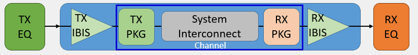
- TX equalization: This is represented by IBIS-AMI model for TX
- Channel: it may further divided into three sub-sections:
- TX IBIS: This is typically an IBIS model of either output or IO type. That is, it include both I/V and V/T tables to drive the channel downstream.
- Passive interconnect: Package, transmission line, connectors, cables etc all belong here.
- RX IBIS: This is IBIS model of input or terminator types. Both Tx and Rx also include C_Comp parasitic.
- Rx equalization: This is represented by IBIS-AMI model for RX
The reason why these sections are cascaded is due to the point-to-point, source synchronous natures of a SERDES system. As a result, IBIS-AMI spec. is also defined accordingly as shown below:
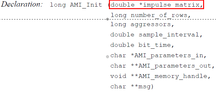
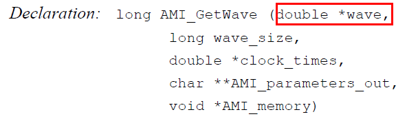
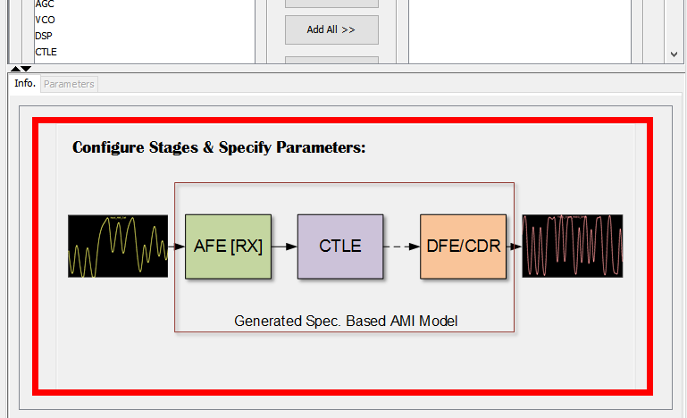
In both the AMI_Init and AMI_GetWave functions defined the spec, the input and output is the same memory address (passed by reference) pointing to an array. Thus signal are transmitted stage-by-stage not only between different sections of a SERDES channel, but also inside different building blocks of either Tx or Rx EQ circuits: