

Top-down AMI modeling flow via StatEye:
The “top-down” modeling flow via StatEye or SPISim_Link web apps is shown below. It supports both Bit-by-bit and statistical model analysis done to SPISim’s spec. AMI models or those from 3rd party vendors. Channel including Tx/Rx IBIS can be defined behaviorally so its impulse or pulse response will be causal. In channel sim suite, Invoke “Schematic”->”Model what-if” ->”StatEye what-if” will bring up this StatEye dialog:
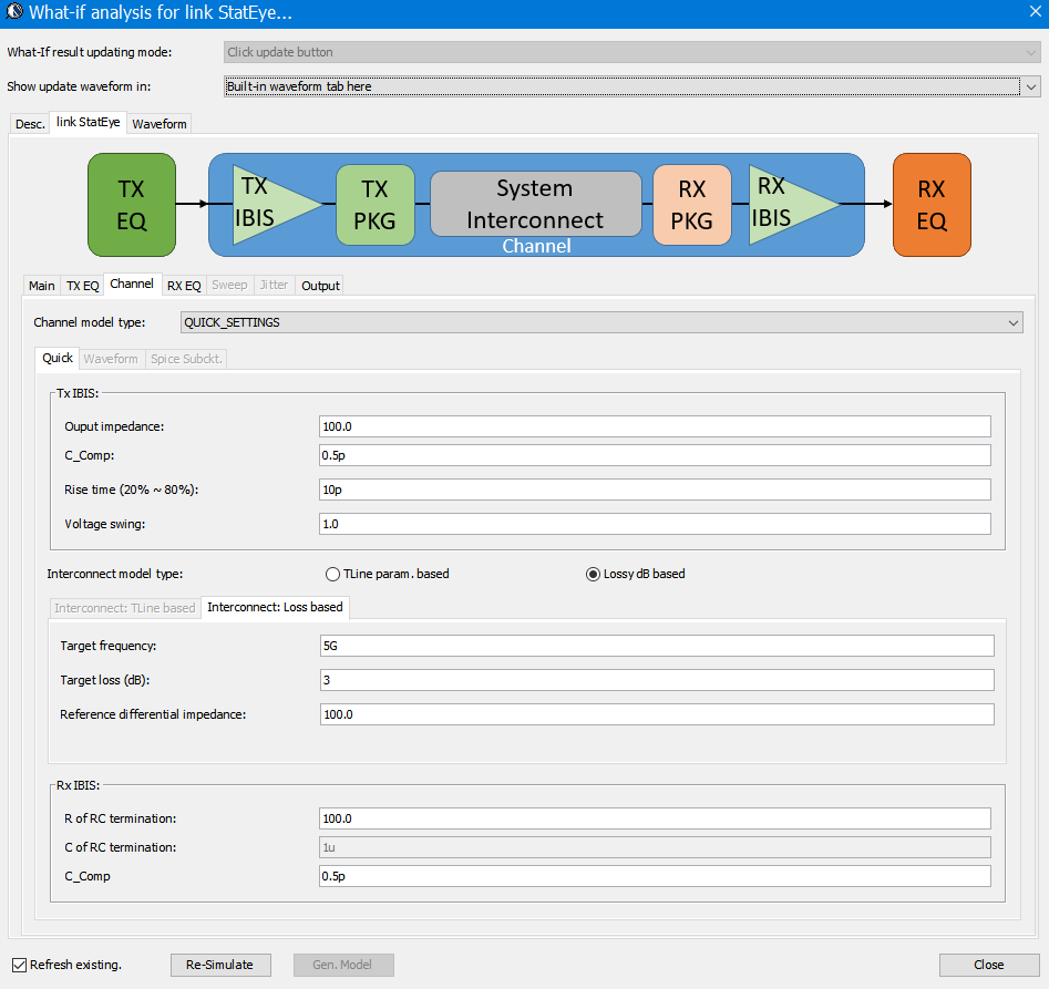
It has several sub-tabs to support configuration of simulation, TxEQ, channel, RXEQ and outputs. User can specify to display waveform in built-in plot panel or as a standalone window in VPro together with various BER measurements.
Main settings:
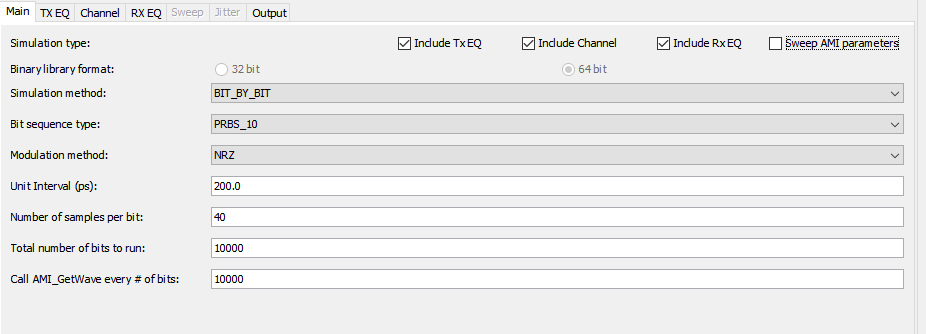
User can choose among Bit-By-Bit mode or statistical modes with desired PRBS source. Tx/Channel/Rx stages may be selected enabled or disabled to bypass their effects.
Tx EQ Setup:
In both Tx and Rx tabs, user can choose to either use quick typical settings for these stages, use 3rd party vendor’s models or generate a customized one from SPISim’s spec. model generation.
A typical Tx EQ include de-emphasis of different taps: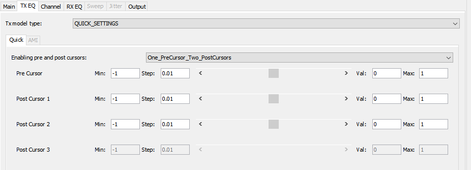
For a 3rd party vendor’s model, specify its .ami and .dll/.so files:
Their .ami parameters can be further customized via a tree-line navigator: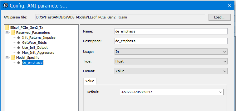
SPISim’s spec. AMI model support full customized EQ configurations: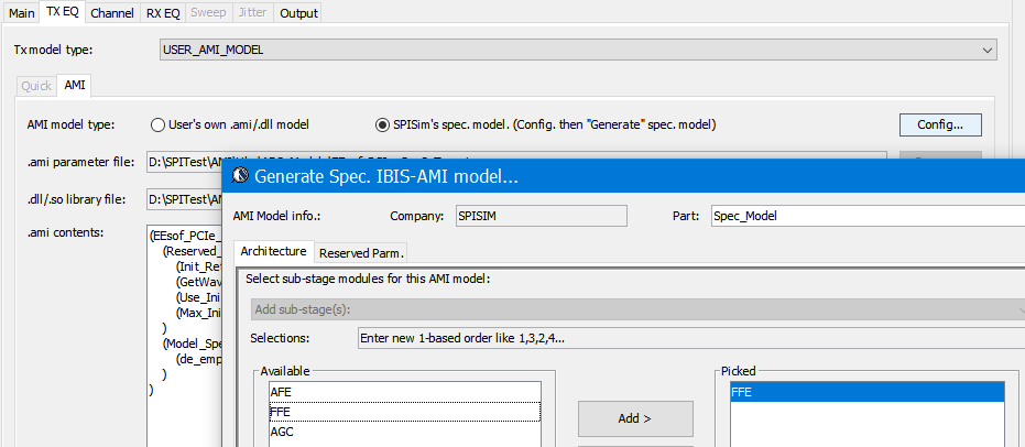
The “Spec. model generation” features will be discussed in more details [HERE].
Channel Setup:
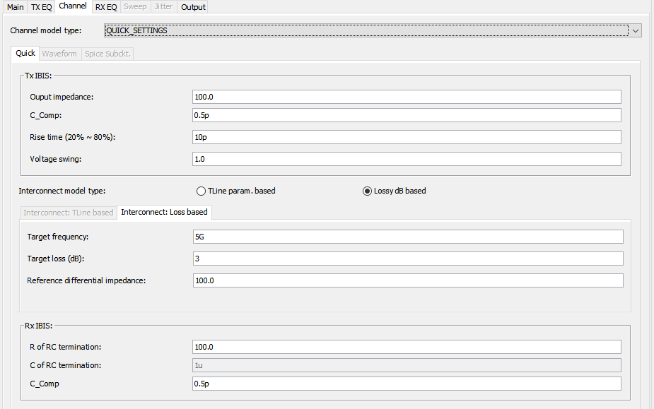
Channel’s response can be specified as behaviors parameters, imported as an impulse file or a touch stone s-parameters. For the behavioral model, both lossy channel and t-line type parameters can be used:
Lossy channel: User can specify differential impedance, desired loss and the targeted frequency. A causal built-in transmission line models will be “stretched” or “shrunk” in length to meet this spec. Transfer functions results from Tx and Rx IBIS (analog front ends) are then applied to this lossy interconnect to form the full lossy channel.
Transmission line: PCB’s physical properties such as length, propagation speed and loss tangent etc can be used. These values may be obtained via the layer stackup analysis or PCB spec. at hand.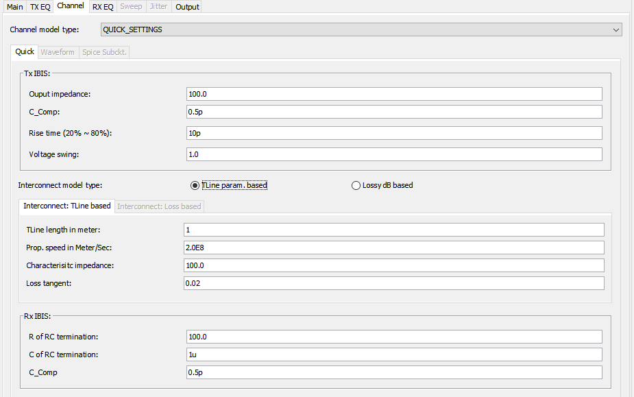
Rx EQ Setup
Similar to Tx EQ, Rx EQ tab also supports various EQ model to be used. A typical Rx EQ model may contain one or more stages of CTLE, DFE and CDR: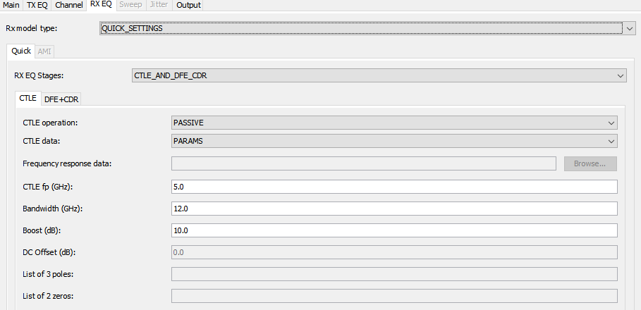
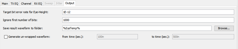
Output settings:
User can also specify the desired BER spec target for eye height measurement in the post-processing stage:
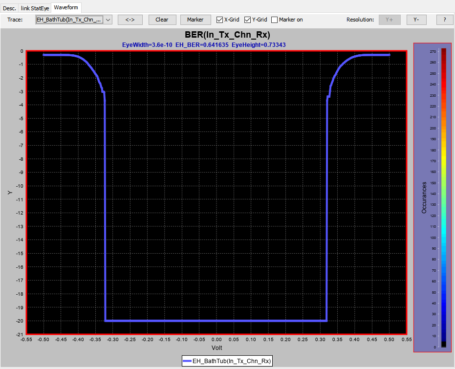
Simulate:
With one click , channel stateye simulation will be done and resulting waveform can be displayed in place, so is BER eye-height measurement:

AMI Model generation:
User may adjust the Tx or Rx EQ settings and iterate this process until the result meet the design requirements. If the “Quick Settings” mode is used, these parameters can then be used to construct a spec-based AMI models of that type (FFE, CTLE+DFE+CDR etc) using SPISim’s spec. model generation. If the “Spec. model” is used in the Tx/Rx tab, then the AMI models is already generated in the specified working directory and is ready to be used.