

Here at SPISim, we provide AMI modeling service in addition to the developed EDA tools. Companies interested in AMI service are mostly IC/IP vendors. They need to provide AMI model in particular so that their user, system companies which use their ICs, can perform the design and analysis. Oftentimes, our client is only interested in AMI modeling for either Tx or Rx circuit because that’s where their IC design resides. However, they also often found later on that in many scenarios, it actually takes “two” models to be useful for their users. In this post, I will talk about some of such “paring-off” cases so that interested reader may be well informed when such modeling needs arise.
Tx and Rx:

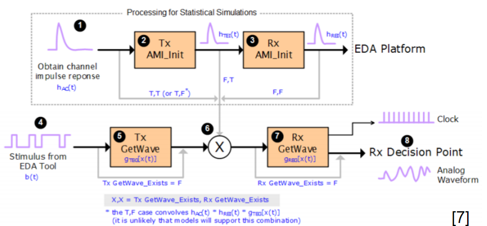
The topology shown above is most commonly used for link analysis. At the Tx and Rx ends, user often is asked to specify corresponding IBIS models. Most definitely, they need to specify AMI model and associated AMI parameters. The interconnect in the middle is generalized here… it can be Tx package, main route, connector and Rx package etc represented in either separate models or cascaded S-parameter. The whole purpose of interconnect here is to provide an impulse response so that when link simulator is operating in either “Statistical” or “Bit-By-Bit” modes, AMI models at the Tx and Rx ends will be able to process accordingly. The analysis flow an AMI-compatible simulator should follow is described in details in section 10.2 of the IBIS spec. User should find that in those descriptions, and almost all the tutorial documents on-line such as the one below from KeySight, both Tx and Rx AMI models are both required to be part of the analysis.
Thus, the first “paring-off” in AMI modelings is each Tx needs an Rx AMI models to work… at least mostly. From this perspective, this is very different from traditional spice-based simulation, where you may have Tx/Rx part in either IBIS, transistor circuit or behavior/Verilog-A modeling format and can simulate without any issue.
So what if you have only either Tx or Rx AMI model? It will be tricky (depends on the simulator) if not possible in many cases. So we here at SPISim often have to provide a “dummy” AMI model in additional to the one ordered. As a “dummy” model, it is a simple pass-through without doing anything. When combined with pass-through S-param or interconnect, it will be very straight forward and clear to test and validate delivered AMI model’s performance. When all the spec. are met (e.g. EQ levels), then the user can add real interconnect and Tx/Rx AMI models from other vendors to proceed the design process.
(A pass-through “Dummy” AMI model implements AMI API but without any implementation body or just don’t change those variables passed by reference)
Repeater:
IBIS version 6.0 includes technical advances such as mid-channel repeaters documented in BIRD 156.3. Repeater is often used in longer SERDES channel such as PCIe or HDMI etc. There are two types of repeaters: redriver and retimer.
- Redriver: A redriver performs signal conditioning through equalization, providing compensation for input channel loss from deterministic jitter such as inter-symbol interference.
- Retimer: A retimer is a mixed-signal device that includes equalization functions plus a clock data recovery (CDR) function to compensate both deterministic and random jitter, and in turn transmit a clean signal downstream.
It’s easy to see the “paring” part within a repeater: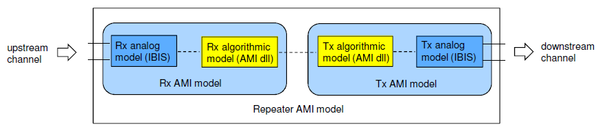
Within a repeater, Rx sits at the front to receive signals from upstream, then pass to Tx part of the repeater to transmit again toward the downstream. So one really can’t work without the other. Plus also “paired” Tx AMI at upstream and final Rx AMI at the end of the downstream, it takes at least four AMI models in most cases to start the analysis. More than one repeaters are also allowed so the number of “paired” AMIs can grow. The proper analysis sequence when repeater(s) is involved is also documented in 10.7 of the spec.
So far as repeater being an “electrical” component is concerned, there may be no such needs to probe signals between Rx and Tx within a repeater. However, when we model an optical link as a repeater (shown below from Agilent slides), then thing becomes much more interesting:
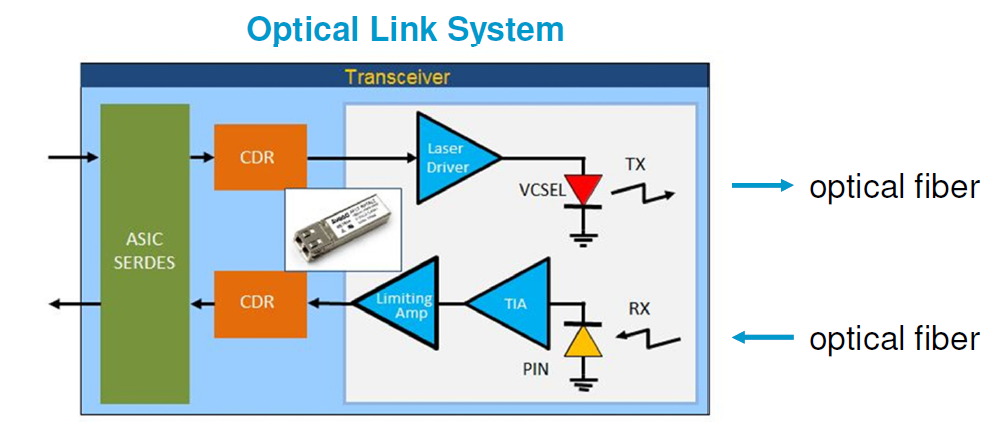
We handled such a case just recently… an optical transceiver used in an (electrical) system may be modeled as a repeater. Having that said, please note that in “optical” world, Tx is now again at the front of the repeater as laser is used to light the optical fiber to transmit signal toward Rx (now the 2nd part of the repeater). So a potential confusion may happen here when optical and electrical worlds meet. In addition, there might be two other considerations:
- There may be needs to probe signal between optical’s Tx and Rx ends, which can be single-ended-like (optical pulse in mili-watt)
- Users of such optical module based repeater may only focus on design at the upstream side, the downstream side or both. In the former two situations, they may not have AMI models at the other side.
The first one above is tricky to solve… mainly due to the non-differential nature of signals in a link simulator. Until now, if one reads the AMI portion of the IBIS spec, he/she should notice that the signal mentioned are always differential. So while there is no problem to create an AMI model handling single ended signals, how the probing/analysis goes really depends on simulator being used. Having that said, with DDR adopting AMI methodology, the single-ended signal support should happen very soon.
To accommodate needs of different possible users of our clients, we make use of the “pass-through” dummy model again and proposed the following different AMI models combinations:
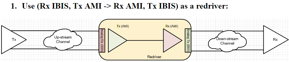
In usage scenario 1: The modeled Tx and Rx optical ends (each have their own circuitry) are assembled accordingly. Thus if a simulator can handle “single-ended-like” optical signal in between, then this model can be used directly.
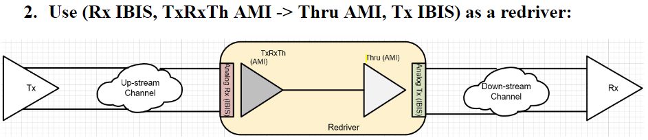
In usage scenario 2: The signal between optical ends within a redriver is not of concern and the support of single-ended-like signal is uncertain. In this case, we “lumped” the TxRx together and put it at the front of the redriver. The second half of the redriver is a simple pass-through. As input and output from the first part are always differential, it will meet the expectation of the simulation flow documented in the spec.
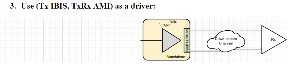
In usage scenario 3: we assume the user is only interested in the downstream end and have only Rx AMI model. In such a case, a repeater will not work because it’s lack of the up-stream. So we combined the created TxRx here and make it a transmitter AMI.
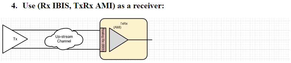
In usage scenario 4: we assume the user is only interested in the upstream portion and only have Tx model. Similar to scenario 3, we combine the TxRx of the optical models and make it a receiver AMI.
In the “paring-off” for a repeater, there are two points worth mentioning:
- Unless DFE/CDR are being modeled and thus retimer, distinction between Tx and Rx EQ are often blur particular when they both are LTI. For example, either Tx or Rx can have a FFE EQ and CTLE of a Rx is also just a passive filter. In such case, a model can be used as either a Tx or Rx (like scenario 3 and 4). The only thing needs to pay attention to is the jitters assignment as AMI parameters for Tx and Rx’s jitters are different.
- We want to cover all usage scenarios and make our client happy. However, we also don’t want to over burden SPISim engineers too much in creating too many different AMI models. Thus as mentioned in previous post, the architecture of AMI modeling becomes important. When done properly.. (such as in our cases 🙂 ), we can simply cascade stages easily at the .ami file level without even rewriting C/C++ codes or any re-compilation.
IBIS-AMI and IBIS:
When we focus on more technically challenging AMI models, we often forgot still important role a traditional IBIS model will play in link analysis. Simply put, the accuracy of an IBIS model still impacts the final results (e.g. BER eye) greatly.
The normal process of the link analysis starts with “link characterization”. Mostly this involves a time domain simulation of driver driving through interconnect with receiver analog front-end (no EQ) connected to obtain the pad to pad step response. Then this step response is differentiated to obtain the impulse response. Finally AMI models are brought into play by convolving with impulse response (LTI or statistics mode) or processing with bit response sequence (NLTV or bit-by-bit mode). In this characterization stage, no EQ (i.e. no AMI) is involved. It’s is their “analog front-end”, i,.e. IBIS models or corresponding spice/behavioral models being used. Thus, the accurate modeling of this portion does impact the processed link analysis results.
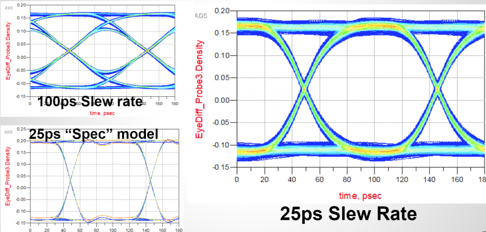
In the picture above, eye plots of identical AMI model yet each with different IBIS models are shown. It’ clearly seen how IBIS’s VT waveform and IV curves affect the eye openings width and height. Thus the third scenarios we want to emphasis of IBIS/AMI “paring-off” is the AMI model and their corresponding IBIS model.
SPISim is a relative small EDA/consulting company comparing to others such as Agilent, Cadence or Mathsoft (matlab). These companies each have their own AMI modeling solutions and cost much much higher when comparing to our offerings. However, when we look into their AMI product details, it’s not easy for us to find (or maybe even not there?) how the IBIS portion will be handled. As an AMI model is mostly used for SERDES application, differential or current-mode-logic (CML) design is often involved. If one reads chapter 4 of IBIS cookbook carefully (available at the IBIS website), he/she should find that the process of differential IBIS modeling is more complicated than the simple single-ended IBIS buffer. Thus when considering the importance of “paring” between AMI and IBIS, one should really take this into account. An AMI model without proper analog front end will definitely come back to haunt you during validation stage. Interested reader regarding differential IBIS modeling may also refer to our previous post or our 2016 Asian IBIS summit paper.