In previous post, I mentioned about the “IBIS cook-book” as a good reference for the analog portion of the buffer modeling. Unfortunately, when it comes to the equalization part, i.e. AMI, there is no similar counterpart AFAIK. For the AMI modeling, the EQ algorithms need to be realized with algorithms/procedures implemented as spec. compliant APIs and written in C language. These functions then need to be compiled as a dynamic library in either dynamic link libraries (.dll on windows) or “shared objects (.so on linux-like). Different compiler and build tool has different ways to create such files. So it’s fair to say that many of these aspects are actually in the computer science/programming domains which are outside the electrical or modeling scopes. It is unlikely to have a document to detail all these processes step-by-step.
In this post, instead of writing those “programming” details, I would like to give a high-level overview about what different steps of the AMI modeling process are… from end to end. Briefly, they can be arranged in the following steps based on execution order:
- Analog modeling
- Prepare collateral
- Define architecture
- Create models
- Model validation
- Channel correlation
- Documentation
The following sections will describe each part in details.
Analog modeling:
Believe it or not, the first step of AMI modeling is to create proper IBIS models… i.e. its analog portion. This is particular true if circuit being modeled belongs to TX. A TX AMI model is equalizing signals which includes its own analog buffer’s effect measured at the TX pad. So if there is no channel (pass-through) and it’s under nominal loading condition, the analog response of the TX will be the signals to be equalized. That is to say, without knowing what will be equalized (i.e. what the model’s analog behavior is), one can’t calculate the TX AMI model’s EQ parameters.

Take the plot above as an example. This is a FFE EQ circuit. The flat lines indicated by two yellow arrows are different de-emphasis settings, thus controlled by AMI. However, the rising/falling slew rate, wave shape and dc levels etc as circled in red are all analog behaviors. Thus an accurate IBIS model must be created first to establish the base lines for equalization. Recently, BIRD 194 has been proposed to use touch-stone file in lieu of an IBIS model… still the analog model must be there.
For a RX circuit, it may be easier as an input buffer is usually just a ESD clamp or terminator. Thus it doesn’t take much effort to create the IBIS model. Interested people may see my previous posts regarding various IBIS modeling topics.
Prepare collateral:
AMI’s data can be obtained from different sources: circuit simulation, lab/silicon measurement or data sheet. For simulation case, simulation must be done and the resulting waveform’s performance needs to be extracted. These values will serve as a “design targets” based on whitch AMI model’s parameters are being tuned.
For example, this is a typical TX waveform and measured data:
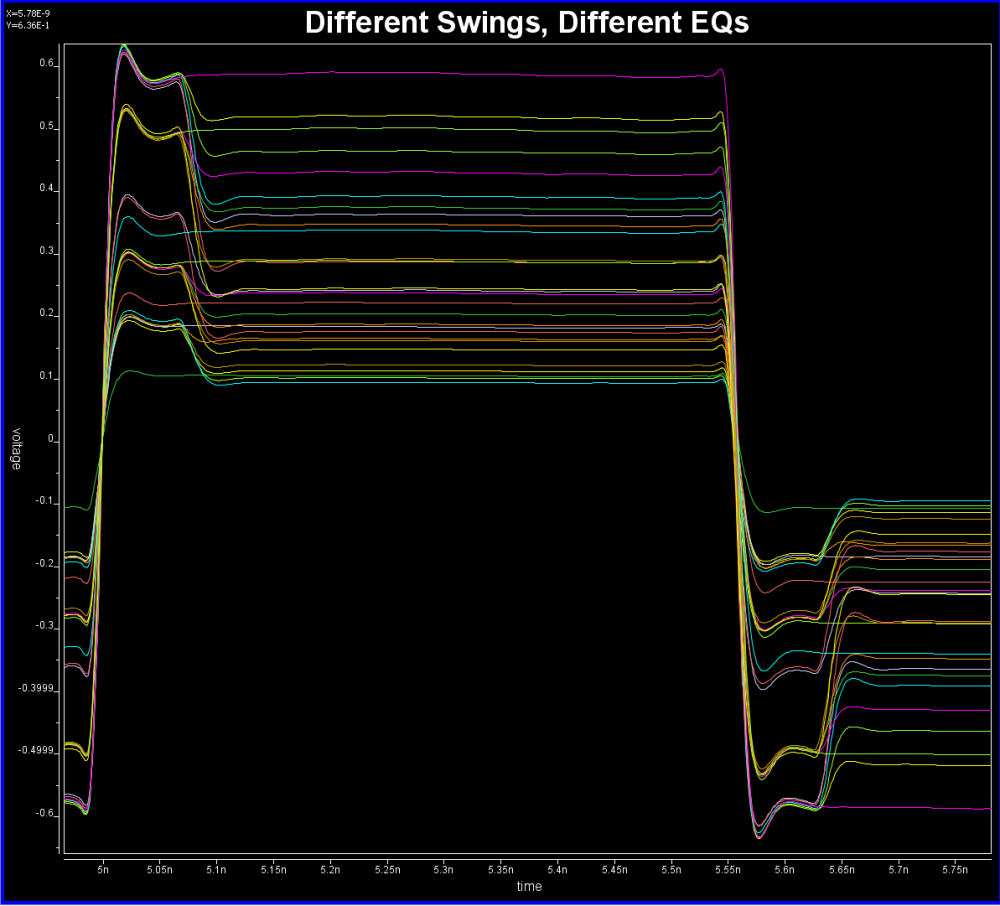
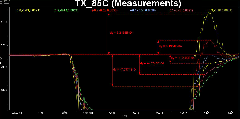
Various curves have been “lined-up” for easy post-processing. Using our VPro, we batch measured the value at the 5.3ns for different curves and created a table: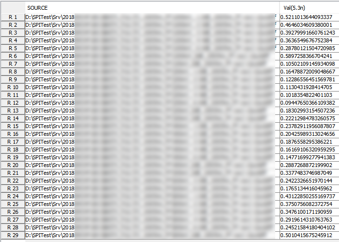 Similarly, data collected from measurement needs to be quantified. This may be done manually and maybe labor intensive as the noise is usually there:
Some of the circuits may have response is in frequency domain. In this case, various points (DC, fundamental freq. 2X fundamental etc) needs to be measured like above.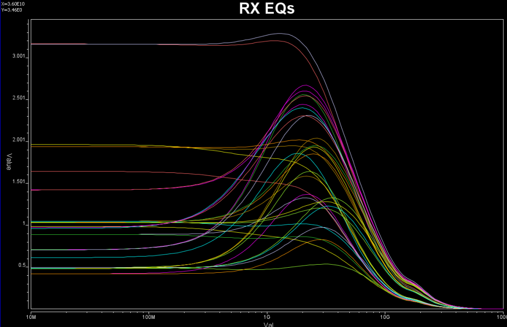
If it’s from data sheet, then the values are already there yet there may be different ways to realize such performance. For example, equations of different zeros and poles locations may all have same DC gain or gain at particular frequencies, so which one to pick may depending on other factors.

Define architecture:
Based on the collateral and the data sheet, the modeler needs to determine how the AMI models will be built. Usually it should reflect the IC’s design functions so there are not much ambiguity here. For example, if the Rx circuit has DFE/CDR functions, then the AMI models must also contain such modules. On the other hand, some data my be represented in different ways and proper judgement needs to be made. Take this waveform as an example: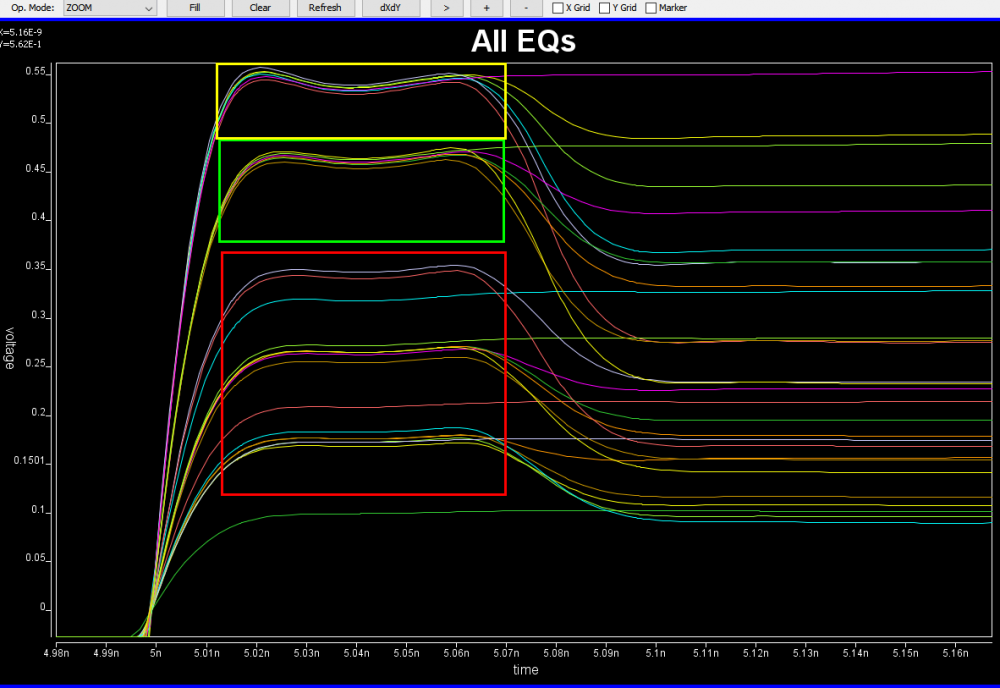
It’s already very obvious that it has a FFE with one post-tap. However, since the analog behavior needs to be represented by an IBIS model, then one needs to decide how these different behaviors, boxed in different colors, should be modeled. They can be constructed with several different IBIS models or a single IBIS model yet with some “scaling” block included so that IBIS of similar wave shapes can be squeezed or stretched. For a repeater, oftentimes people only care about what goes into and what comes out of this AMI model. The abilities to “probe” signals between a repeater’s RX and TX may be limited by the capabilities of simulator used. As a result, a modeler may have freedom determining which functions go into Rx and which go to Tx. In some cases, same model yet with different architecture needs to be created to meet different usage scenarios. An example has been discussed in our previous post [HERE]
Create models:
Once architecture is defined, next step is the actual C/C++ implementation. This is where programming part starts. Ideally, building blocks from previous projects are there already or will be created as a module so that they can be reused in the future. Multiple instance of the same models may be loaded together in some cases so the usage of “static” variables or function need to be very careful. Good programming practice comes into play here. I have seen models only work with certain bit-rate and 32 samples per UI. That indicates the model is “hard-coded”… it does not have codes to up-sample or down-sample the data based on the sampling-interval passed in from the API function. Accompanied with writing model’s C codes are unit testing, source revision control, compilations and dependencies check etc. The last one is particular important on linux as if your model relies on some external libraries and it is not linked statically, the same model running fine on developer’s machine will not even pass golden checker at user’s end…. because the library is not available there. Typically one will need to prepare several machines, virtual or not, which are “fresh” from OS installation and are the oldest “distros” one is willing to support. All these are typical software development process being applied toward this AMI modeling scope.
After the binary .dll/.so files are generated, then next step is to assemble a proper .ami files. Depending on parameter types (integer, values, corners etc), different flavors of syntax are available to create such file. In addition, different EDA simulators has different ways to present the parameter selections to its end user. So one may need to choose best syntax so that choices of parameter values will always be selected properly in targeted simulators. For example, if one already select TYP/MIN/MAX corner for the IBIS model, he/she should not have to do so again for the AMI part. It doesn’t make sense at all if a MIN AMI model will be used with MAX corner IBIS model… the corner should be “synchronized”.
Once the model is ready, next step is to tune the parameters so that each of the performance target will be matched. Some interface, such as PCIe, has pre-defined FFE tap weights so there are no ambiguities. In most cases, one need to find the parameter’s values to match measured or simulated performance. Such tasks is very tedious and error prone if doing manually and process like our “AutoTune” will come very handy:
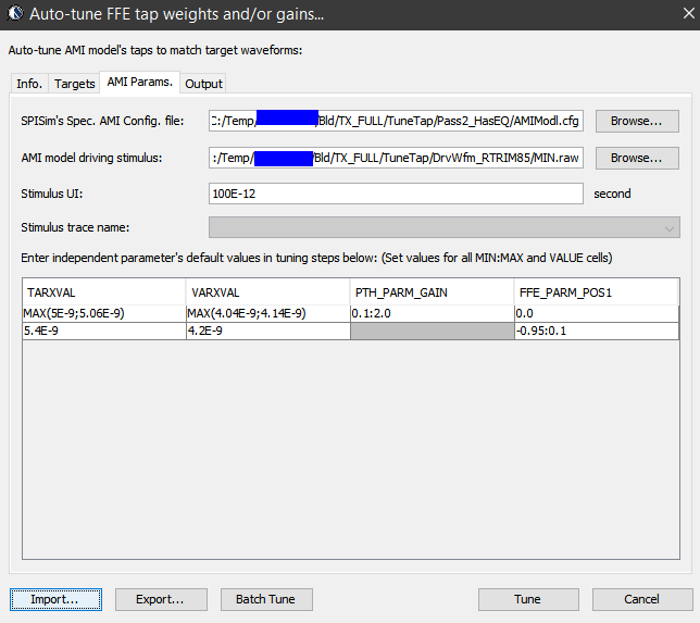
Basically, our tool let user specify matching target and tool will use bisection algorithm to find the tap values. Hundred of cases can be “tuned” in a matter of minutes. In some other cases, grid search may be needed.
Model validation:
Just like traditional IBIS, the first step of model validation is to run it through golden checker. However, one needs to do so on different platforms:

The golden checker didn’t start checking the included AMI binary models until quite recently. Basically it loads the .ibs file, identifies models with AMI functions, then check the .ami file syntax. Finally, the checker will load the associated .dll/.so files. Due to the fact that different OS platform loads binary files differently, that means certain models (e.g. .dll) can only be checked on associated platform (e.g. Windows). That’s why one needs to perform the same check on different platforms to make sure they are all successful. Library dependencies or platform issues can be identified quickly here. However, the golden checker will not drive the binary file. So the functional checks described in next paragraph will be next step.
Typically, an AMI model have several parameters. To validate a model thoroughly, all combinations of these parameters values need to be exercised. We can “parameterize” settings in a .ami file like below:
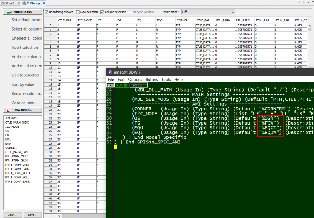
Here, pattern like %VARIABLE_NAME% is used to create a .ami template. Then our SPIMPro can be used to generate all combinations of possible parameter values and create as a table. There can usually be hundreds or even thousands cases. Similar to the process described in “Systematic approach mentioned in my previous post”, we can then generate corresponding .ami files for all these cases. So there will be hundreds or thousands of them! Next step is to be able to “drive” them and obtain single model’s performance. Depending on the EDA tools, most of them either do not have automation capability to do this in batch mode or may require further programming. In our case, our SPIMPro and SPIVPro have built-in functions to support this sweeping flow in batch mode all in the same environment. SPISimAMI model driver is used extensively here! Once each case’s simulation is done, again one needs to extract the performance then compare with those obtained from raw data and make delta comparison.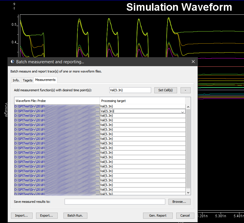
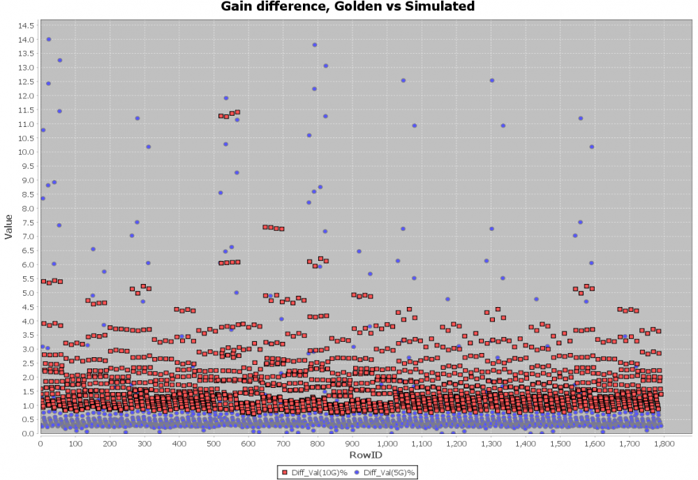
A scattering plot like below will quickly indicate which AMI parameter combinations may not work properly in newly created AMI models. In this case, one needs to go back to the modeling stage to check the codes then do this sweep validation all over again.
Channel correlation:
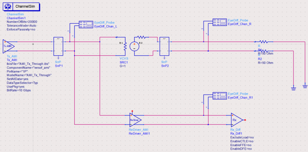
The model validation mentioned in previous section is only for a single model, not the full channel. So one still needs to pick several full channels set-up to fully qualify the models. A caveat of the channel analysis is that it only shows time domain data regardless the flow is “statistical” or “bit-by-bit”, that means it is often not easy to qualify frequency domain component such as CTLE. In this case, a corresponding s-parameter whose Sdd12 (differential input to differential output) is represented by this CTLE AMI settings can be used for an apple-to-apple comparison, like schematic shown below:
Another required step here is to test with different EDA vendor’s tool. This presents another challenge because channel simulator is usually pricey and it’s rarely the case that one company will have all of them (e.g. ADS, HyperLynx, SystemSI, QCD and HSpice etc). Different EDA tools does invoke AMI models differently… for example, some simulator passes absolute path for DLL_Path reserved parameter while others only sent relative path. So without going through this step, it’s difficult to predict what a model will behave on different tools.
Documentation:
Once all these are done, the final step is of course to create an AMI model usage guide together with some sample set-ups. Usually it will starts with IBIS model’s pin model associations and some performance chart, followed by descriptions of different AMI parameters’ meaning and mapping to the data sheet. One may also add extra info. such as alternatives if the user’s EDA tool does not support newer keyword such as Dll_Path, Dll_ID or Supporting_Files etc. Waveform comparison between original data (silicon measurement vs AMI results) should also be included. Finally it will be beneficial to provide instructions on how an example channel using this model can be set-up in popular EDA tools such as ADS, HyperLynx or HSpice.

Summary:
There you have it.. the end-to-end AMI modeling process without touching programming details! Both AMI API and programming languages are moving targets as they both evolve with time. Thus one must continue honing skills and techniques involved to be able to deliver good quality models efficiently and quickly. This is a task which requires disciplines and experience of different domains. After sharing these with you readers, do you still want to do it yourself? 🙂 Happy modeling!

